


- sales/support
Google Chat:---
- sales
+86-0755-88291180
- sales01
sales@spotpear.com
- sales02
dragon_manager@163.com
- support
tech-support@spotpear.com
- CEO-Complaints
zhoujie@spotpear.com
- Only Tech-Support
WhatsApp:13246739196
- Purchase/Shipping/Refund
WhatsApp:13424403025
Raspberry Pi CM-STEREO-VISION-BOARD User Guide
Instruction
This binocular stereo vision expansion board is specially designed for Raspberry Pi Compute Module, compatible with CM3 / CM3 Lite / CM3+ / CM3+ Lite. It features three camera ports and commonly used ports like DSI and USB, more other peripheral interfaces are also supported through the FPC connector, all in the small size body.
By connecting with various sorts of cameras, combined with the included IMU fill light board, it is easy and flexible to build different Raspberry Pi stereo vision projects such as binocular parallax ranging, facial identification, living object detection, VR video recording, and so on.
Features
- Compatible with Raspberry Pi Compute Module CM3 / CM3 Lite / CM3+ / CM3+ Lite
- Three camera ports, CAM0 port for default use, and CAM1/CAM3 ports are two alternative options selected by GPIO
- Onboard DSI port allows directly connecting with DSI display
- Onboard USB connector, convenient for flashing system image, or used as a regular USB port
- 36PIN GPIO connector comes with adapter board for extending UART port and standard 40PIN Raspberry Pi GPIO
- 24PIN HDMI extended connector comes with adapter board for connecting with HDMI display
- 10PIN GPIO/I2C extended connector, for connecting the included ICM20948 IMU fill light board
- Integrates DS1307 RTC chip, along with CR1220 battery holder
- Comes with acrylic mounting plate and tripod adapter, make it easy to use with a general tripod
What's on board
Stereo vision board
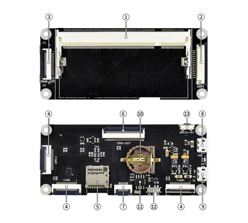
| No. | Symbol | Description |
| 1 | Compute Module interface | 可接入Compute Module 3/3 Lite/3+/3+ Lite |
| 2 | DSI interface | For connecting DSI display |
| 3 | 24PIN HDMI interface | It can connect an HDMI display by the HDMI adapter board. |
| 4 | CSI interface | CAM0:Enabled by default CAM1:Enabled by setting GPIO38 to low CAM3:Enabled by setting GPIO38 to high |
| 5 | Micro SD card slot | For inserting Micro SD card |
| 6 | 36PIN GPIO interface | You can extend classic 40PIN GPIO by the UART adapter board. |
| 7 | 10PIN I2C interface | For connecting ICM20948 board. |
| 8 | USB interface | For writing eMMC or working as a standard OTG interface. |
| 9 | 5V Power input | - |
| 10 | RTC battery holder | For CR1220 battery |
| 11 | DS1307 | RTC chip |
| 12 | USB BOOT ENABLE switch | EN: Writing eMMC DIS:USB interface works as standard OTG interface |
| 13 | User key | - |
UART adapter
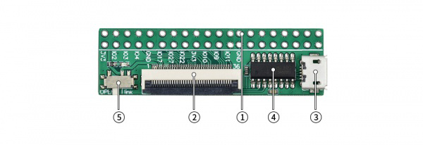
| No. | Symbol | Description |
| 1 | Raspberry Pi GPIO interface | For connecting Raspberry Pi HATs |
| 2 | 36PIN GPIO interface | Connect to Stereo board |
| 3 | USB TO UART interface | For UART shell login or power supply |
| 4 | CH340 | USB to UART chip |
| 5 | Power switch | OPEN:Disable the power function of USB interface Link:The USB to UART interface can be used as a power interface |
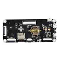
ICM2948 board
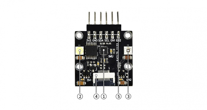
| No. | Symbol | Description | |
| 1 | ICM-20948 | Accelerometer | Resolution: 16 bit |
| Measurement range (configurable): ±2, ±4, ±8, ±16g | |||
| Operating current: 68.9uA | |||
| Gyroscope | Resolution: 16 bit | ||
| Measurement range (configurable): ±250, ±500, ±1000, ±2000°/sec | |||
| Operating current: 1.23mA | |||
| Magnetometer | Resolution: 16 bit | ||
| Measurement range: ±4900µT | |||
| Operating current: 90uA | |||
| 2 | White fill light | controlled via GPIO40 | |
| 3 | 850nm IR fill light | controlled via GPIO41 | |
| 4 | 10PIN I2C connector | for connecting with CM3 base board | |
| 5 | 6PIN I2C header | for connecting with host board | |
User guide
2 Write image
2.1 Write image for Compute Module 3/Compute Module 3+
If you use Compute Module 3 or Compute Module 3+, you should write an image to the internal eMMC
The steps of writing eMMC:
1)Run the RPiboot_Setup software to install the driver. You will get a rpiboot.exe file in the installation directory: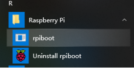
2)Turn the USB SLAVE ENABLE switch into EN
3)Connect the Compute Module 3 or Compute Module 3+
4)Connect the USB interface of STEREO board to PC
6)<font color="#ff0000"Run rpiboot.exe as administrator</font>, PC will recognize eMMC of Compute module as a portable drive.
7)Run Win32DiskImage software to write image to eMMC
Note: If you wrote image to the eMMC before, you need to format it firstly by Panasonic_SDFormatter software
8)After writing, you can disconnect the USB cable, and re-power the STEREO board to start the CM3/CM3+ by connecting 5V power adapter to PWR interface
Note:
- While writing the image, DO NOT write other portable storage drives to avoid conflicting.
- The default user name and password of the image of Raspberry are pi and raspberry.
- The EMMC of CM3+ is extended, which allows CM3+ to install a common desktop image. However, the eMMC of CM3 is only 4G, therefore if you want to write an image to CM3, please choose Raspbian Lite. You can also install GUI for Lite image separately by commands below (network is required):
 sudo apt-get update
 sudo apt-get install raspberrypi-ui-mods
If you cannot write a image to eMMC successfully, you can try the following steps:
- Use Windows 10 PC instead of Windows 7 or Linux.
- Make sure that the Compute module you use is the eMMC version which has one more chip on the backside.
- You should connect a 5V power adapter to the PWR interface.
- Change another USB cable for a try.
- Change to other USB port of PC for a try.
- Try to restart your PC.
- Try to reset the CM3/CM3+ board.
- Try with other PC.
2.2 Write image for Compute Module 3 Lite/Compute Module 3+ Lite
The steps for writing image for Lite version::
1、Donwload image from Raspberry Pi website.
2、Insert TF card to host PC by card reader, the size of the TF card should at least be 8G.
3、Run Win32DiskImager software for writing, it just the same as how you write an image for Raspberry Pi board.
4、After writing, insert the TF card to the card slot of STEREO Board.
3 Connect DSI display
Here we use 4.3inch DSI LCD for example, you can also use official 7inch LCD.
- 1: Power off the STEREO Board
- 2: Connect 15Pin FPC cable to STEREO Board and DSI display
- 3: Connect the power adapter to STEREO Board
- 4: Wait for several seconds to start Raspbian
Note:
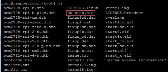
- If you use Raspberry Pi official image, you need to compy dt-blob.bin file to /boot directory
4 Connect HDMI display
Here we use the 7inch HDMI LCD (H) (with case) as example
1、Remove the DSI display, and connect the HDMI adapter board to HDMI interface of STEREO Board
2、Connect the HDMI display(Raspbian default to use DSI display if both HDMI display and DSI display are connected at the same time)
3、Modify config.txt file of TF card, for 7inch HDMI LCD (H) (with case), you should add the following lines to /boot/config.txt file
  max_usb_current=1
  hdmi_force_hotplug=1
  config_hdmi_boost=10
  hdmi_group=2
  hdmi_mode=87
  hdmi_cvt 1024 600 60 6 0 0 0
3、Reboot after modifying.
5 Connect CSI Camera
5.1 Test RPi Camera
- Download the pre-configured image from Waveshare wiki. The image was pre-configured to use two cameras
- Connect camera to CAM0 and CAM1 interface, the cameras which are used here are IMX219-77 Camera。
- Power on Stereo board and test camera:
- Test the camera 1
sudo raspivid -t 0 -cs 0
- Test camera 2
sudo raspivid -t 0 -cs 1
-cs is used to choose camera 0 or 1. The number of camera may be different from the silk screen printing as it is the order of recognized cameras
5.2 Test camera with original image
If you use the original Raspbian image, you should configure an image for using the camera manually.
- Run raspi-config commands to enable the camera. Choose Interfacing Options->Camera->Yes->Finish-Yes and then reboot Raspbian.
- Download the dtb ifile from Raspbrry Pi website website
- After downloading, modify the dts file:
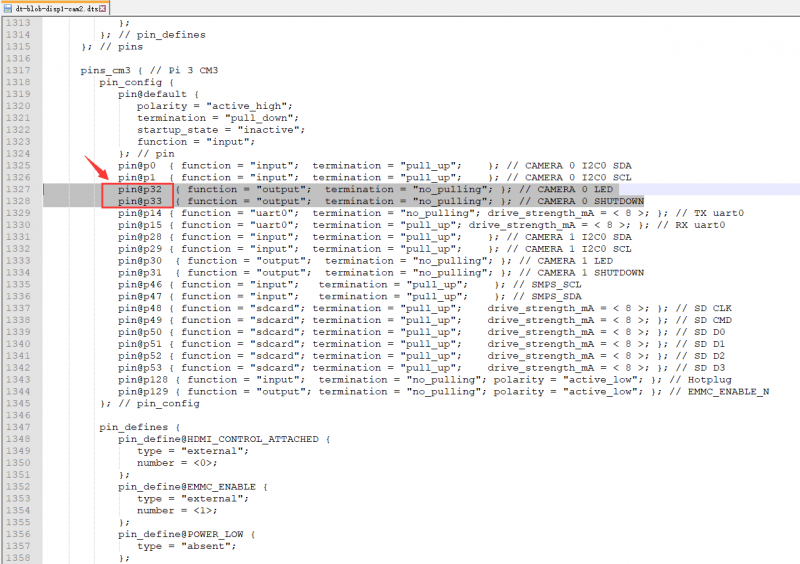
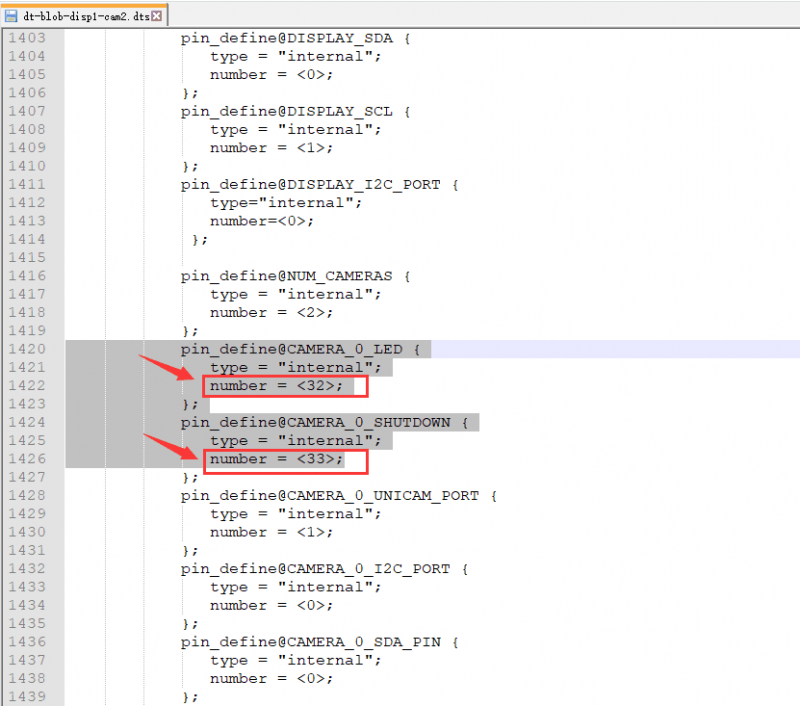
That is you should change LDE and SHUTDOWN from pin2, pin3 to pin32 and pin33.
- After modifying, you need to compile it
dtc -I dts -O dtb -o dt-blob.bin dt-blob-disp1-cam2.dts
- After compiling, the file dt-blob.bin is generated, and you should copy it to boot directory.
- To test camera, you can use commands below:
 sudo raspivid -t 0 -cs 0
 sudo raspivid -t 0 -cs 1
How to use CAM3 interface
You can switch CAM3 and CAM1 by changing the status of GPIO38
Set GPIO38 to High, the CAM3 is enabled.
Set GPIO38 to Low, the CAM1 is enabled.
- Run the following script to switch CAM1 and CAM3
cd ~/CM_STEREO_BOARD
sudo chmod +x CAM3_CAM1_Switch.sh
./CAM3_CAM1_Swtich.sh 1
- ./CAM3_CAM1_Switch.sh 1 Enable CAM3
- ./CAM3_CAM1_Switch.sh 1 Enable CAM1
- Then you can test the camera
sudo raspivid -t 0 -cs 1
6 Test ICM20948
- Download the demo code
wget https://www.waveshare.com/w/upload/d/d8/CM_STEREO_BOARD.zip
unzip CM_STEREO_BOARD.zip
- Connect the ICM20948 board to STEREO board by 10PIN FFC cable
- Enable I2c interface
sudo raspi-config
- Choose Interfacing Options -> I2C -> Yes->OK
- Check I2c address
i2cdetect -y 1
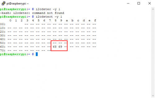
- The module is connected properly if both 68 and 69 are detected..
- 68 is the i2c address of RTC, and 69 is ICM20948 board's
- Run the following command to test ICM20948
cd ~/CM_STEREO_BOARD/10Dof-D_Demo/
sudo make
sudo ./10Dof-D
- The terminal will print the data of the ICM20948 chip after running the code.
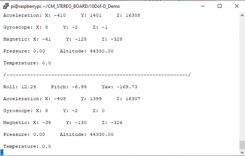
- You can press Ctrl+c to stop the code.
7 Test RTC
- STEREO board has backup battery holder for RTC, you can mount an CR1220 in it.(Battery should be purchased separately)
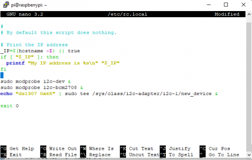
- Modify rc.local file
sudo nano /etc/rc.local
- Add the following lines in the front of exit0
sudo modprobe i2c-dev &
sudo modprobe i2c-bcm2708 &
echo "ds1307 0x68" | sudo tee /sys/class/i2c-adapter/i2c-1/new_device &
- Reboot
sudo reboot
- Check the i2c address again, you will find that the address 68 is changed to UU, it is normal
- Read RTC clock
sudo hwclock -r
- If the time is wrong, please configure the Locations and time zone then test it again.
- You can also write the RTC time to the system.
sudo hwclock -s
7 Test LEDs and key
An Infrared LED and a white LED is integrated on ICM20948 board, here we use the user key to control them.
- Run the following commands
cd ~/CM_STEREO_BOARD/
sudo python KEY_LED.py
- The infrared LED lights on after running the codes, then you can press the key to toggle the LEDs.
- The white LED is bright, we recommend you to shelter it with paper when testing.
- You can pres Ctrl+C to stop the code
8 Test the UART adapter board
- Connect the UART adapter board to STEREO Board by 36PIN FFC cable.
- Connect the USB to UART interface of the UART adapter board to host PC
- Enable Serial shell login function
sudo raspi-config
- Choose Interfacing Options -> Serial -> Yes -> No -> OK
- Reboot Raspbian then you can access the OS by putty software on PC.