- sales/support
Google Chat: zj734465502@gmail.com
- sales
+86-0755-88291180
- sales01
sales01@spotpear.com
- sales02
dragon_manager@163.com
- support
services01@spotpear.com
- CEO-Complaints
manager01@spotpear.com
- sales/support
WhatsApp:13246739196
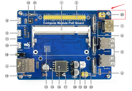
Compute Module PoE Board User Guide
Instruction
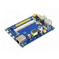
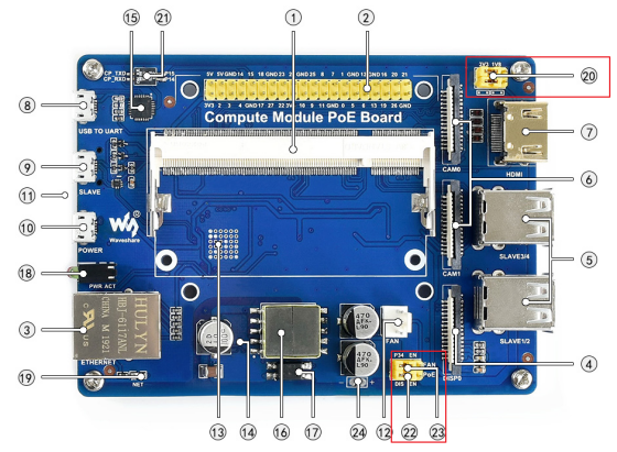
The Compute Module PoE Board is a development board that you can plug a Raspberry Pi Compute Module into, and make use of the resources of Pi more flexibly. With the PoE (Power over Ethernet) feature, and versatile onboard peripheral interfaces, it is suitable for evaluating the Raspberry Pi compute module, also is an ideal choice for end products.
Features
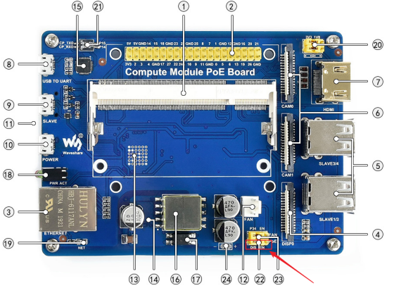
- Raspberry Pi GPIO header, for connecting sorts of Raspberry Pi HATs
- 10/100M auto-negotiation Ethernet port, with PoE enabled
- 4x USB ports, allows connecting more USB devices
- 2x CSI camera interfaces
- Onboard HDMI / DSI interfaces for connecting displays
- Onboard USB TO UART, for serial debugging
- Cooling fan interface, autorun on power-up OR controlled by IO pins
- Adopts isolated SMPS (Switching Mode Power Supply)
Specification
- Power supply: micro USB port / PoE Ethernet port
- PoE power input: 37V ~ 57V DC in
- PoE power output: 5V 2.5A DC out
- Network standard: 802.3af PoE standard
- Dimensions: 114mm × 84.4mm
- Mounting hole size: 3.2mm
User guide
Power
- 1. PoE power
- To enable POE function, you should set the PoE jumpers to EN side
- When using PoE function, this module supports DC 27V ~ 57V input, and voltage output is 5V and 2.5V.
- To check PoE, you can test pad 24.
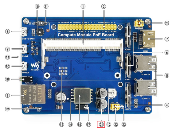
- You can measure the voltage of pad 24 by multimeter, if the voltage is about 5.25V, the PoE function works normally, otherwise, it doesn't.
- 2. DC power
- Except PoE, you can also power on the Compute PoE board by DC 5V 2.5A (or above) power adapter.
- You should set the jumper 22 to the DIS side and connect a power adapter to the POWER interface.
Write image
- 1. If you use Compute Module 3 or Compute Module 3+, you should write an image to the internal eMMC
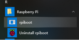
- Run rpiboot_setuo ( please download it from #Resource) to install driver. After installing, you will get an rpiboot.exe file in the installation directory.
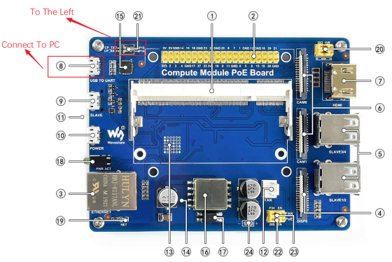
- Set jumpers 20 to the left side, set jumpers 22 and jumpers to the left side as well.
- Insert your Compute module to PoE board.
- Connect SLAVR interface of PoE board to your PC
- Connect Power interface of PoE board to power adapter
- Run rpiboot.exe as administrator, PC will recognize eMMC of Compute module as a portable drive.
- Run WinDiskImager.exe software to write image to eMMC.
- After writing, you can disconnect the USB cable, and re-power the POE board to start the CM3/CM3+.
【Note】
- While writing image, DO NOT write other portable storage drive to avoid conflicting.
- The default user name and password of image of Raspberry is pi and raspberry.
- The EMMC of CM3+ is extended, which allows CM3+ to install a common desktop image. However, the eMMC of CM3 is only 4G, therefore if you want to write image to CM3, please choose Raspbian Lite. You can also install GUI for Lite image separately by commands below (network is required)
sudo apt-get update
sudo apt-get install raspberrypi-ui-mods
- 2. If you use Compute Module 3 Lite or Compute Module 3+ Lite, you should write the image to SD card just like common Raspberry Pi
- To write image, you should prepare an SD card (16G or larget) and card reader.
- Use Win32DiskImage.exe software to write image to SD card. (It is same as how you write image for Pi 3B)
- After writing, insert the SD card to the card slot of PoE Board.
Connect DSI display
Here we use 4.3inch DSI LCD for example, you can also use official 7inch LCD.
- Please power off PoE board
- Connect 15Pin FPC cable to Compute Module PoE Board and DSI display'
- Connect power adapter to PoE board
- Wait for several seconds to start Raspbian.
Note:
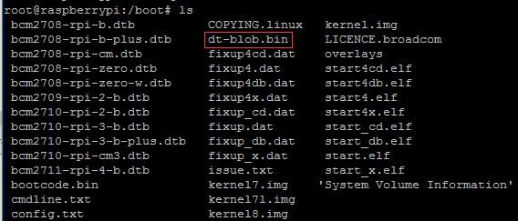
- If you use Raspberry Pi official image, you need to compy dt-blob.bin file to /boot directory
- You can download DT_Bin file here
Connect HDMI display
Here we use 7inch HDMI LCD (H) as examples
- Remove the DSI display if you have connected. Connect the HDMI display to PoE board (both HDMI interface and Touch interface should be connected)
- Modify /boot/config.txt fuke:
 max_usb_current=1
 hdmi_force_hotplug=1
 config_hdmi_boost=10
 hdmi_group=2
 hdmi_mode=87
 hdmi_cvt 1024 600 60 6 0 0 0
- Reboot
Connect CSI camera
- 1. Test camera with pre-configured image
- 【Note】: Unlike the official Compute Module IO Board V3, the camera pins of this Compute PoE Module are not conflicted with 40Pin GPIO.
- Download the pre-configured image from Waveshare wiki. The image was pre-configured to use two cameras
- Connect RPi FPC camera to PoE board
- Power on PoE board and test camera
- Test the camera 1
sudo raspivid -t 0 -cs 0
- Test camera 2
sudo raspivid -t 0 -cs 1
【Note】:-cs is used to choose camera 0 or 1; 0 for CAM1 and 1 for CAM0,
- 2. Test camera with original image
- If you use the original Raspbian image, you should configure an image for using the camera manually.
- Modify /boot/config.txt file, add statement to it
dtparam=arm_i2c
- Run commmand sudo raspi-config. choose Interfacing Options -> Camera -> Yes
- Download dts file from Raspberry Pi website, and copy it to Rasbian
- After downloading, modify the dts file
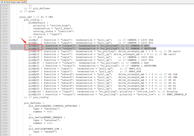
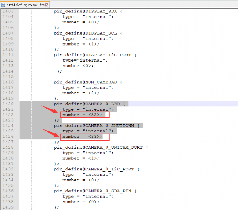
- That is you should change LDE and SHUTDOWN from pin2, pin3 to pin32 and pin33.
- After modifying, you need to compile it
dtc -I dts -O dtb -o dt-blob.bin dt-blob-dualcam.dts
- To test camera, you can use commands below:
sudo raspivid -t 0 -cs 0
sudo raspivid -t 0 -cs 1
Connect colling fan
- 1. Directly enable fan
The 12 interface is Fan port for Fan-4010-5V。
- To directly enable cooling fan, you need to set the jumper 23 to the right side.
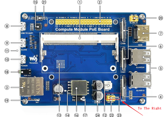
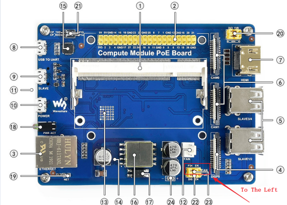
- 2. Control fan speed based on CPU temperature
- To control fan based on CPU temperature, you should set the jumper 23 to the left side
- edit /boot/config.txt file:
sudo nano /boot/config.txt
- Add a line at the end:
dtoverlay=gpio-fan,gpiopin=34,temp=55000
- Reboot. After rebooting, when the CPU temperature is higher than 55 degrees Celsius, the fan will be turned on (the first parameter 34 indicates that the BCM number 34 pin is used to control the fan, and the second parameter 55000 indicates the temperature critical value * 1000)
- You can check the CPU temperature by the following command, the data divide by 1000 is the current temperature.
cat /sys/class/thermal/thermal_zone0/temp
- You can also check it by watch
watch -n 0.1 cat /sys/class/thermal/thermal_zone0/temp
- 3. Control fan by GPIO
- To control fan by GPIO P34, you should set the jumper 23 to the left side

- To control the fan, you should make a script. Here is script for reference.
#include <bcm2835.h>
#include <stdio.h>
#define PIN 34
int main(int argc, char **argv)
{
    if (!bcm2835_init())
    {
      return 1;
    }

    // Set the pin to be an output
    bcm2835_gpio_fsel(PIN, BCM2835_GPIO_FSEL_OUTP);

    while (1)
    {
        // Turn it on
        bcm2835_gpio_write(PIN, HIGH);

        // wait a bit
        bcm2835_delay(50);

        // turn it off
        bcm2835_gpio_write(PIN, LOW);

        // wait a bit
        bcm2835_delay(50);
    }
    bcm2835_close();
    return 0;
}
- You had better set the frequncy higher than 10Hz, the codes above set it to 10Hz.
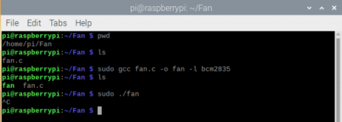
- If you use pre-configured image, this code is saved in the path /home/pi
- You can compile code by command:
sudo gcc fan.c -o fan -l bcm2835
- Run the code
- If you use offical image, you can also download the script manually, before it, pelase install bcm2835 libraries firstly
wget http://www.airspayce.com/mikem/bcm2835/bcm2835-1.60.tar.gz
tar zxvf bcm2835-1.60.tar.gz
cd bcm2835-1.60/
sudo ./configure
sudo make
sudo make check
sudo make install
# For more information of bcm2835 libraries:http://www.airspayce.com/mikem/bcm2835/
Serial port
Compute Module PoE Board integrates CP2102 chip. You can connect the USB to UART interface of PoE board to PC, turn DIP siwtches into CPTXD, CPRXD. In this mode, you can communicate Compute Module board by serial port in PC
Level selection jumpers
- Set the jumpers to left, the voltage level of 40PIN GPIO is 3.3V. and they are 1.8V if you set jumpers to the right.
Indicators
- NET: The network indicator, flashing if network is connectted normally
- PWR: Power indicator, red. The LED keeps on if the board is powered normally, and it flashs if abnormal
- ACT: Green. This is the indicator for TF card read/write. It is flashing when read/write files.