- sales/support
Google Chat: zj734465502@gmail.com
- sales
+86-0755-88291180
- sales01
sales01@spotpear.com
- sales02
dragon_manager@163.com
- support
services01@spotpear.com
- CEO-Complaints
manager01@spotpear.com
- sales/support
WhatsApp:13246739196
- HOME
- >
- ARTICLES
- >
- Common Moudle
- >
- ESP
ESP32-C6-DEV-KIT-N8 User Guide
Software
CH343
UART
Flash
Schematics
Datasheet
ESP32-C6
CH343
Overview
The ESP32-C6-DEV-KIT-N8 is a compact microcontroller development board with multiple peripheral interfaces.
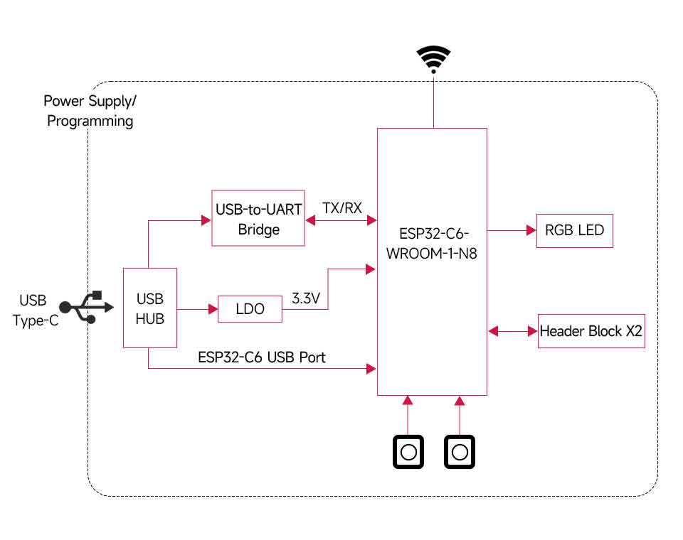
In terms of hardware, it adopts the ESP32-C6-WROOM-1 module with a RISC-V 32-bit single-core processor. It supports up to 160MHz clock frequency with built-in 320KB ROM, 512KB HP SRAM, and 16KB LP SRAM. Onboard CH343 UART and CH334 USB HUB chips, it supports USB and UART development at the same time via a USB-C port. Compatible with the pinout of the ESP32-C6-DevKitC-1-N8 development board, it is more convenient to use and expand a variety of peripheral modules.
Comes with online examples and tutorials for the ESP-IDF development environment, so that you can easily and quickly get started and apply it to the product.
Features
- Adopts ESP32-C6-WROOM-1-N8 module with RISC-V 32-bit single-core processor, up to 160MHz main frequency, built-in 8MB Flash.
- Integrated 320KB ROM, 512KB HP SRAM, 16KB LP SRAM, and 8MB Flash memory.
- Integrated 2.4GHz WiFi 6, low-power Bluetooth (Bluetooth LE), and IEEE 802.15.4 (Zigbee 3.0 and Thread) wireless communication, with superior RF performance.
- Type-C connector, easier to use.
- Onboard CH343 and CH334 chips can meet the needs of USB and UART development via a Type-C interface.
- Rich peripheral interfaces, compatible with the pinout of the ESP32-C6-DevKitC-1-N8 development board, offer strong compatibility and expandability.
- The castellated module allows soldering directly to carrier boards.
- Supports a variety of low-power operating states, adjustable communication distance, data rate, and power consumption balance, to meet the power requirements of various application scenarios.
Fuction Block Diagram
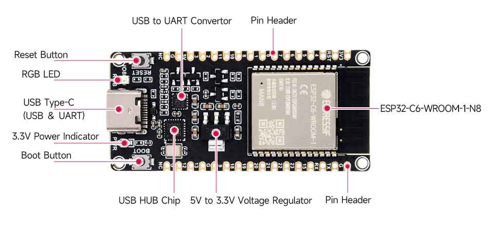
Onboard Resources
Pinout

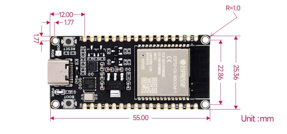
Dimensions
Working with ESP-IDF
The following development system defaults to Windows, and it is recommended to use the VSCode plug-in for development.
Develop with VSCode
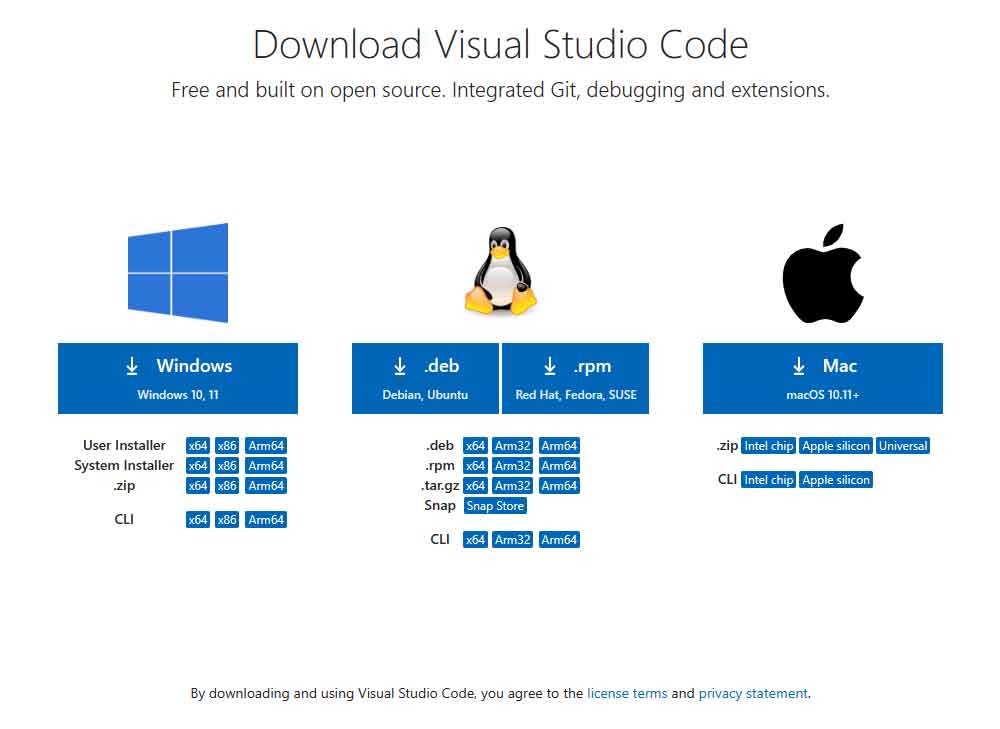
Install VSCode
- Open the VSCode website to download according to the corresponding system and system bits.
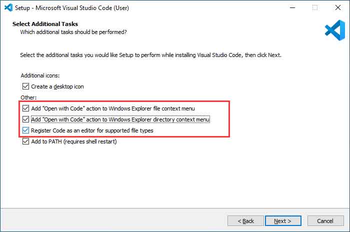
- After running the installation package, the rest can be installed by default, but here for a better experience, it is recommended to check the box here in the 1, 2, and 3 items.
- After enabling the 1 and 2 items, you can directly open the VScode by right-clicking the file or the directory to improve your experience.
- After enabling the 3 items, you can directly select VSCode when choosing how to open,
Install Espressif IDF Plug-in
- Note: Currently the latest version of the plugin is V1.6.4, users can choose the same version as us for a consistent experience!
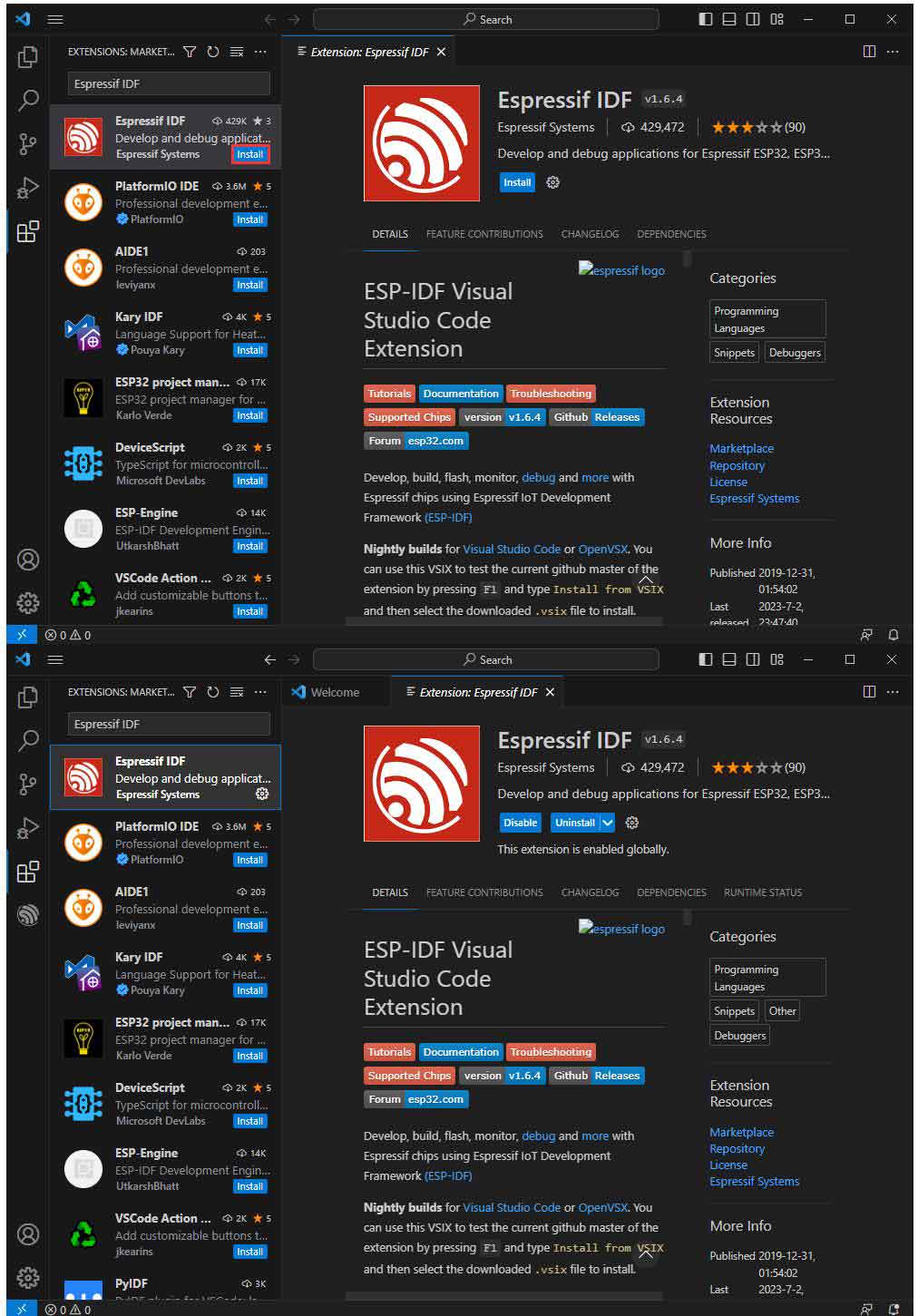
- Open VSCode, use Shift+Ctrl+X to enter the plug-in manager.
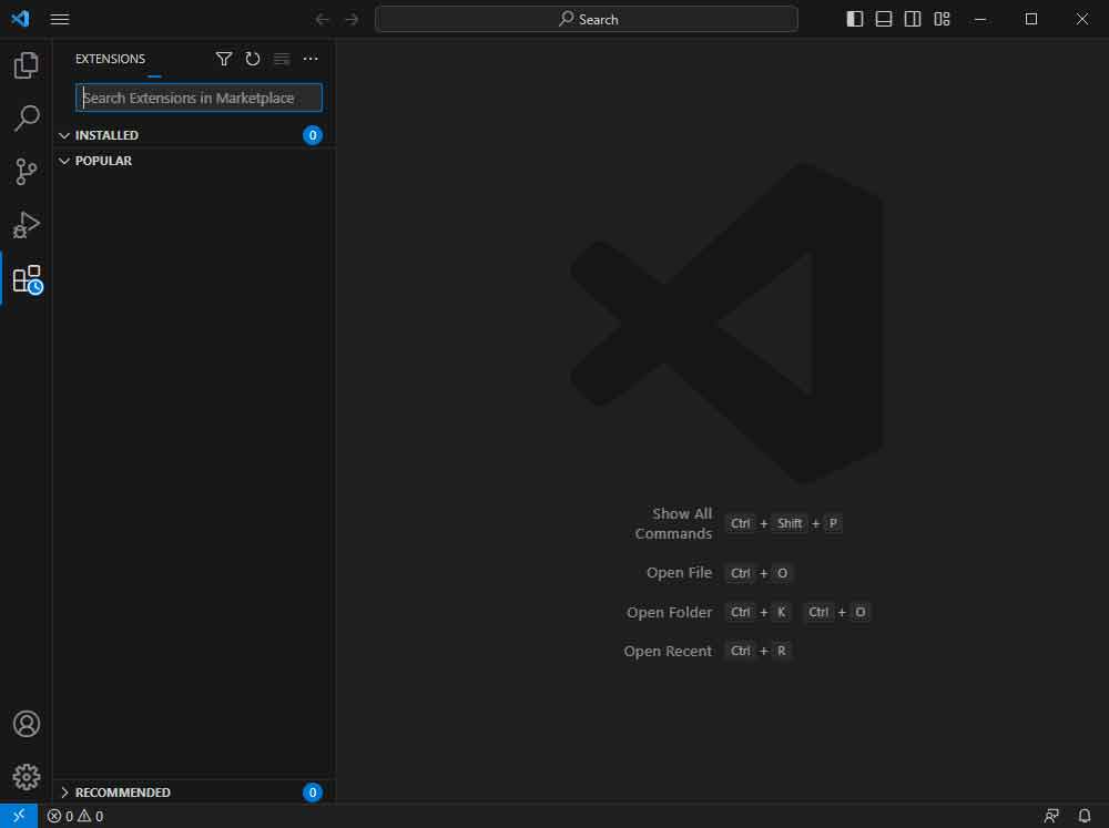
- In the search bar, enter Espressif IDF to select the corresponding plug-in and click "Install".
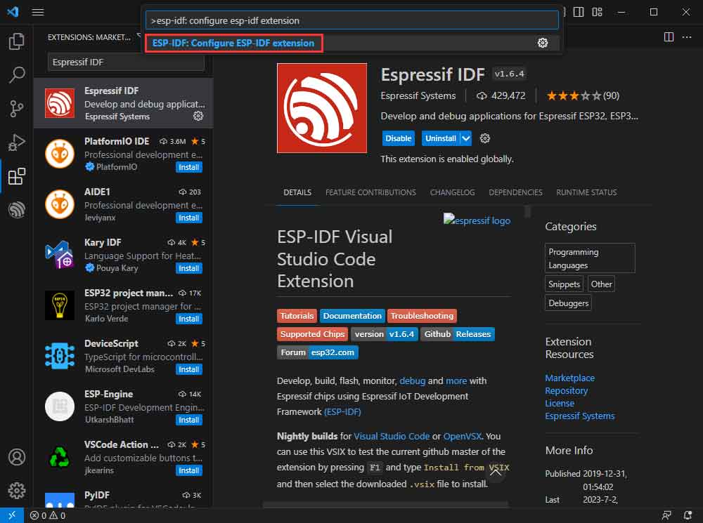
- Press F1 to input:
esp-idf: configure esp-idf extension
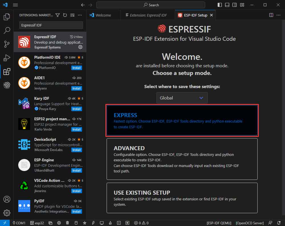
- Select express (this guide is for users who install it for the first time).
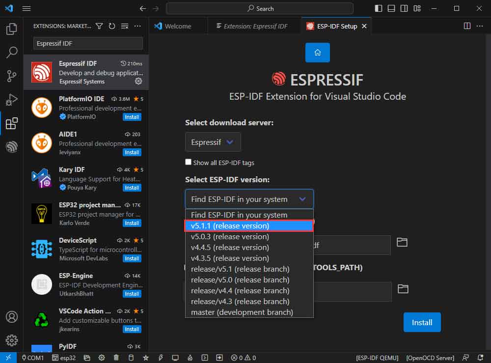
- Select download sever.
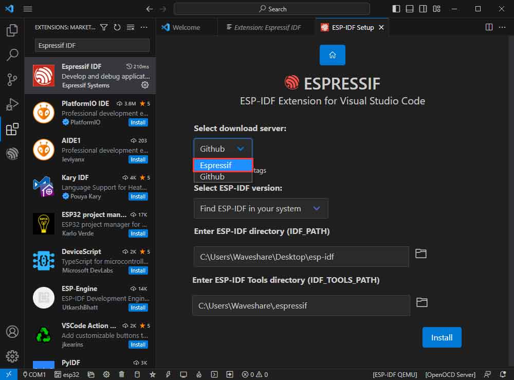
- Select the version of ESP-IDF you want to use now, we choose the latest V5.1.1 (note that only after V5.1 did ESP-IDF start to support ESP32-C6).
- The following two are the installation paths respectively for the ESP-IDF container directory and the ESP-IDF Tools directory.
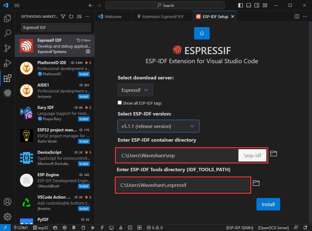
- Note: If you have installed ESP-IDF before, or failed to do so, please be sure to delete the file completely or create a new path without Chinese.
- After configuring, click "Install" to download:
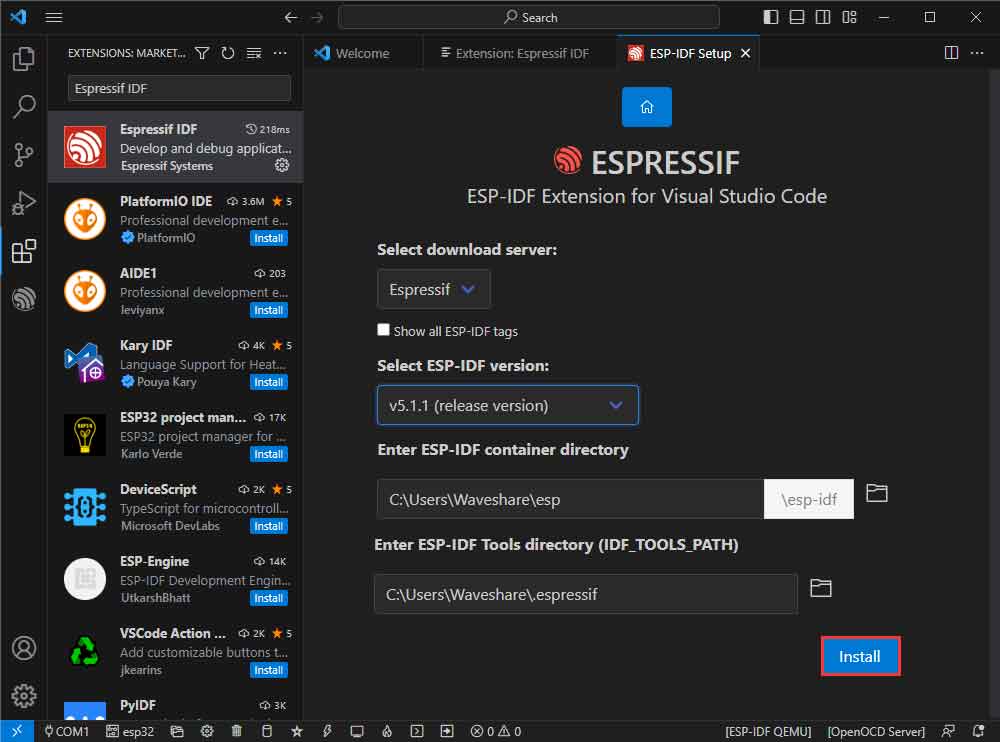
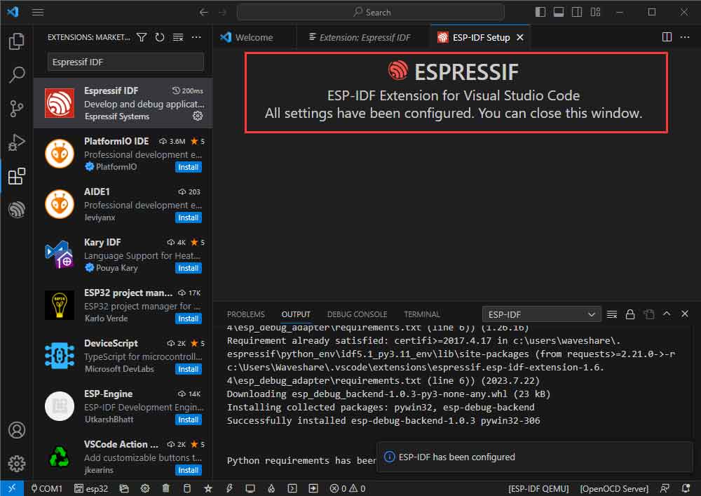
- Enter the download interface, and then it will automatically install the corresponding tools and environment, just wait for a second.
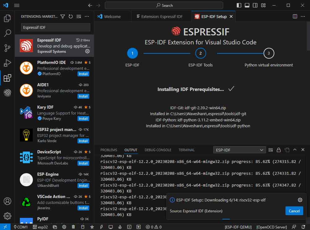
- After the installation is complete, you will enter the following interface, indicating that the installation is finished.
Official Demo Usage GUIDE
Create Demo (Demo Example)
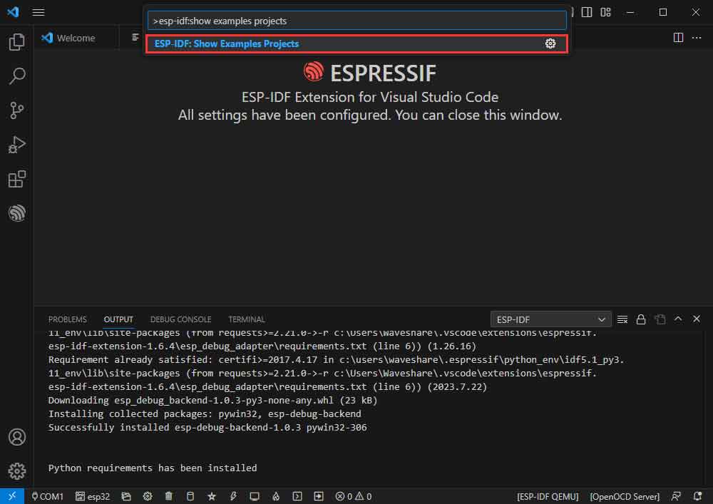
- Press F1 to enter:
esp-idf:show examples projects
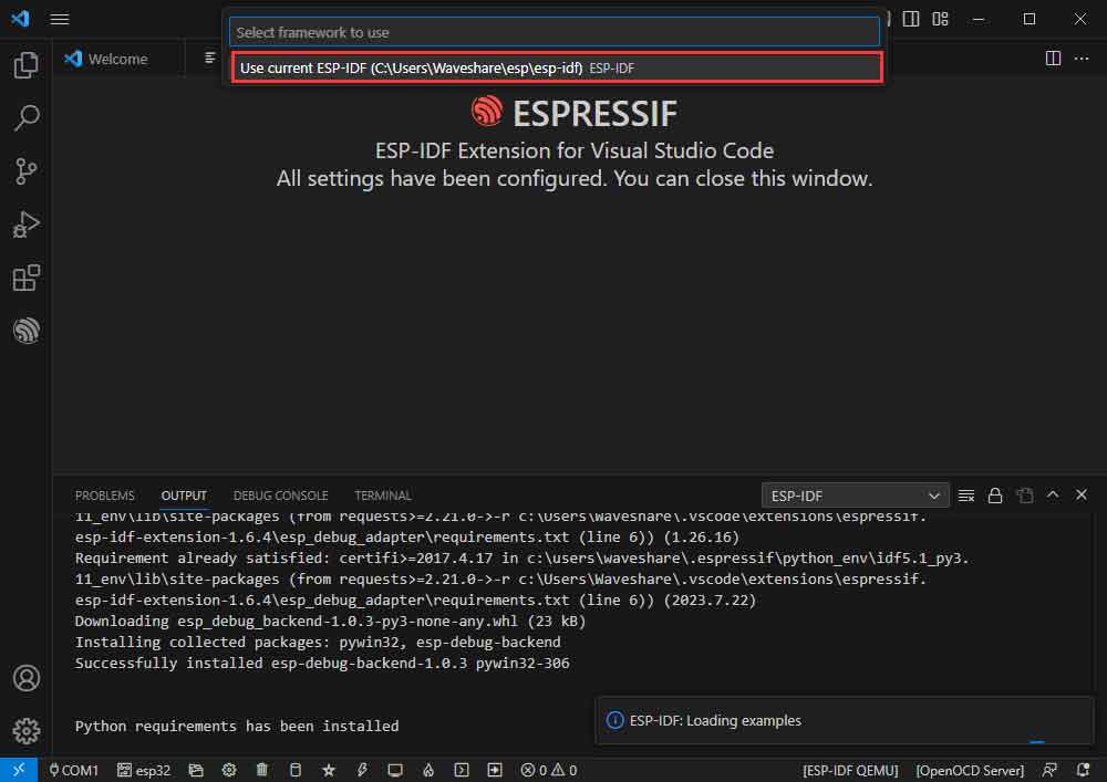
- Select the corresponding IDF version:
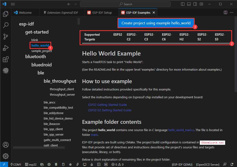
- Take the Hello World demo as an example:
- ①Select the corresponding demo.
- ②Its readme will state what chip the routine applies to (how the demo is used with the file structure is described below, omitted here).
- ③Click to create the demo.
Select the path to place the demo, and the folder name should be aligned with the demo name.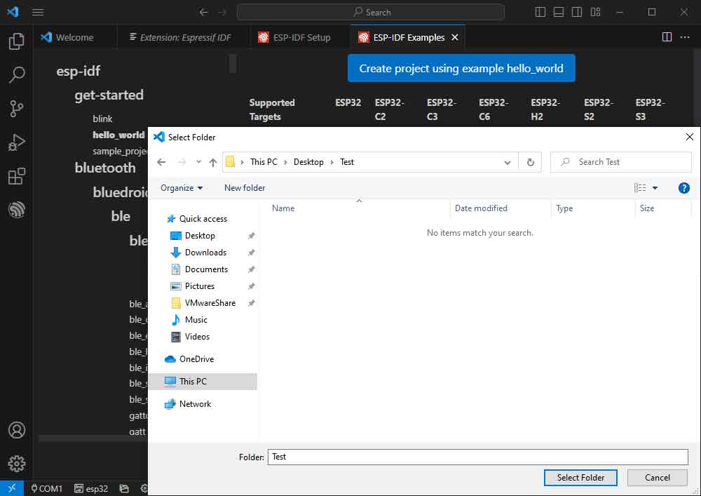
Modify COM Port
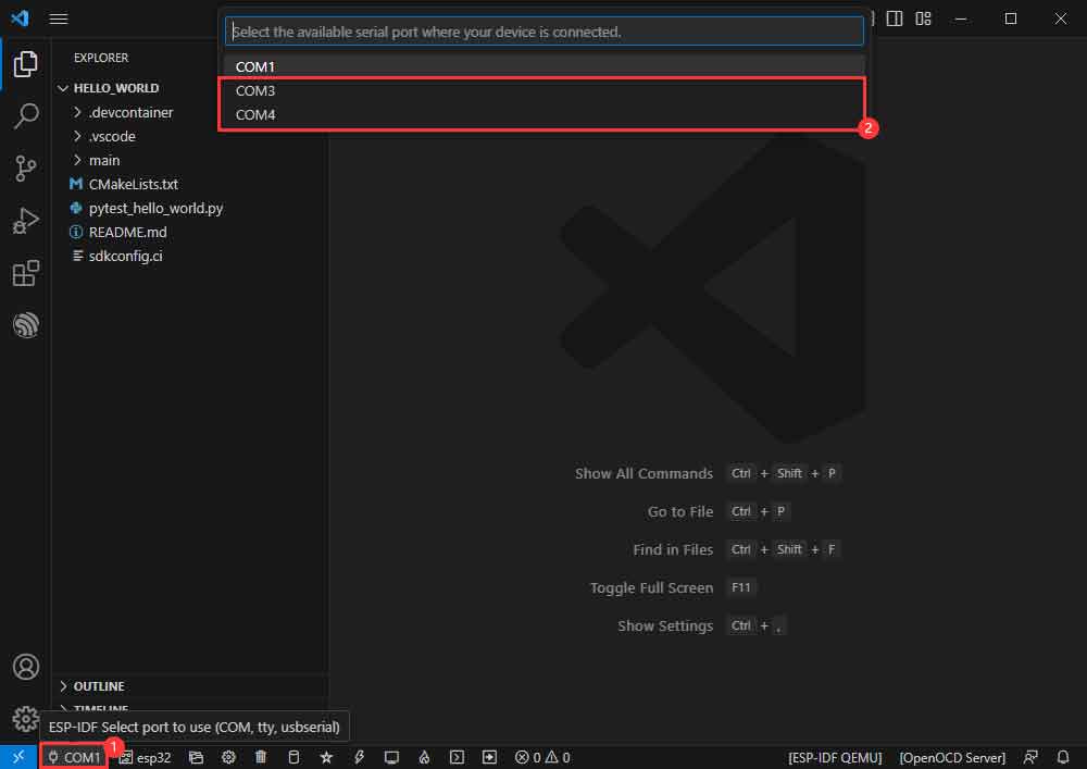
- The corresponding COM ports are shown here, click to modify them.
- Please select the COM ports according to your device. It is recommended to use the COM port corresponding to the USB connector. (You can view it from the device manager.)
- In case of a download failure, please press the reset button for more than 1 second and wait for the PC to recognize the device again before downloading once more.
- Select the project or demo to use:
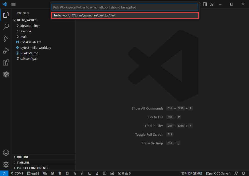
- Then we finish the modification of the COM ports.
Modify the Driver Object
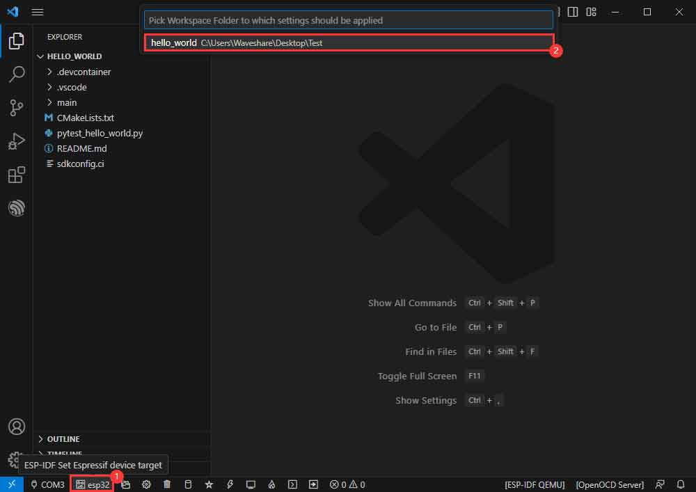
- The driver object is displayed here, and you can modify it by clicking on it.
- Select the project or demo to use.
- Wait for a minute after clicking.
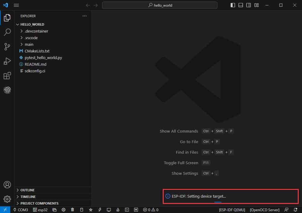
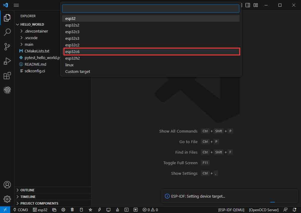
- Select the object we need to drive, which is our main chip ESP32C6.
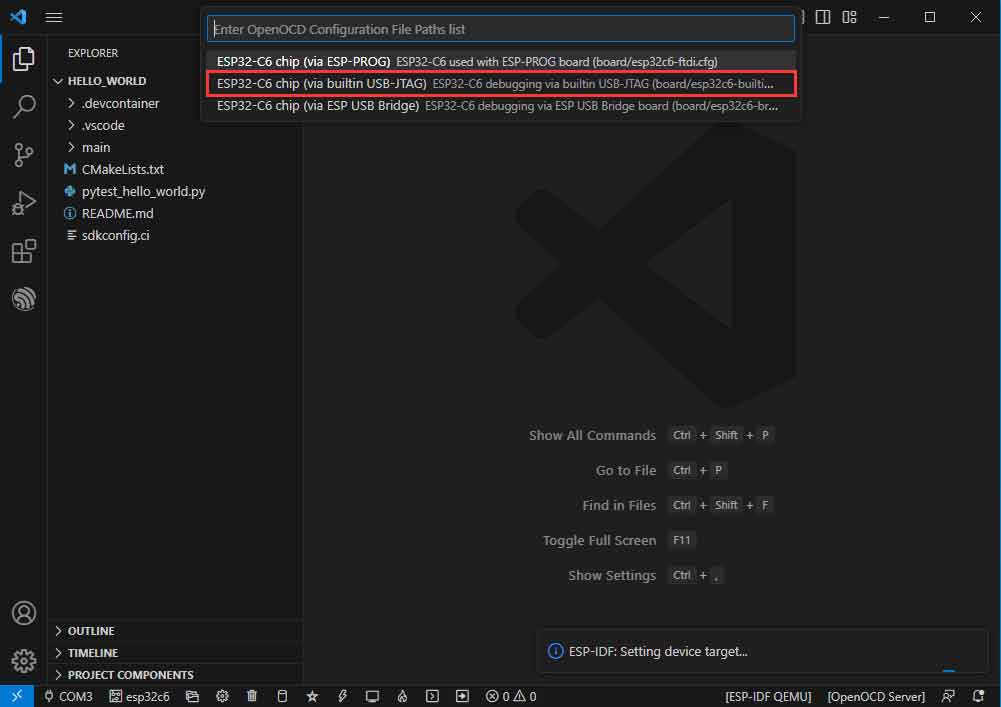
- Choose the path to openocd, it doesn't affect us here, so let's just choose one at random.
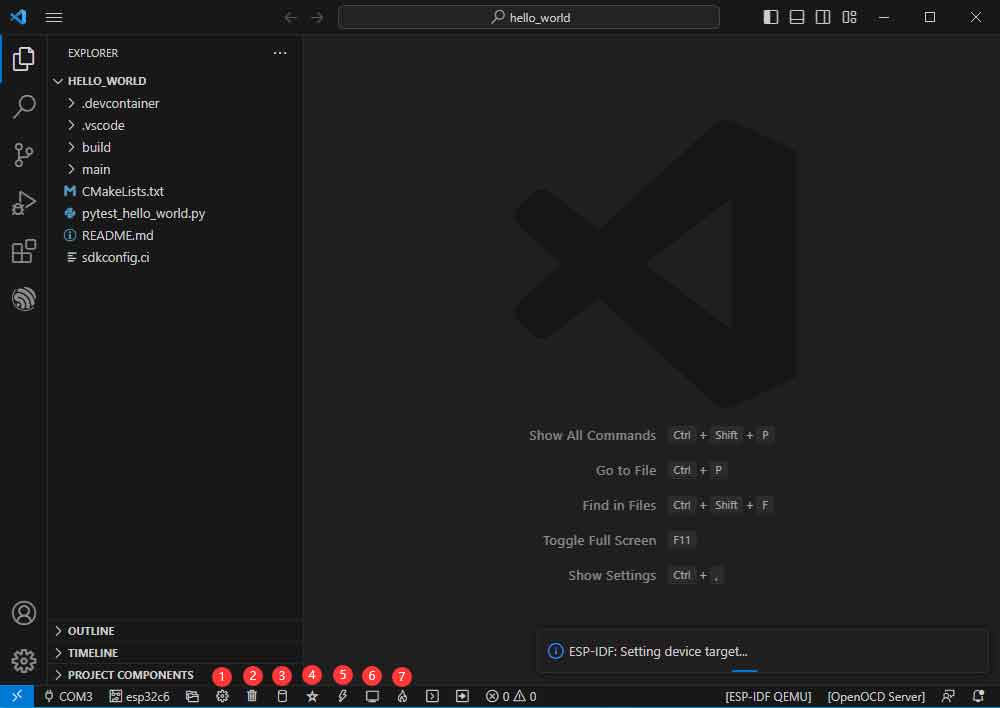
The Rest of the Status Bar
- ①SDK configuration editor, supports modifying most functions of ESP-IDF.
- ②All cleanup, and clear all compiled files.
- ③Compile.
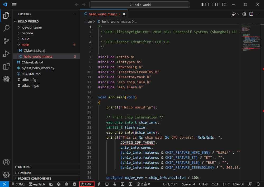
- ④Current download mode, default is UART.
- ⑤Flash the current firmware, please do it after compiling.
- ⑥Open the serial port monitor, used to view the serial port information.
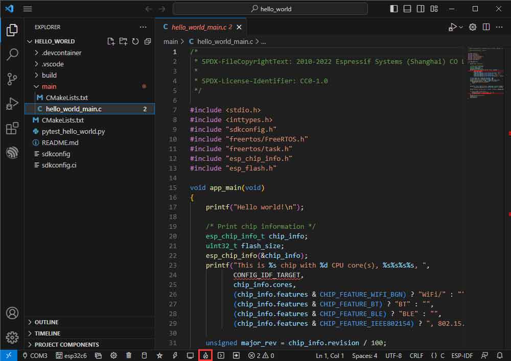
- ⑦All-in-one button, compile, burn, open the serial monitor (most commonly used for debugging).
Compile, Program, Serial Port Monitoring
- Click on the all-in-one button we described before to compile, program, and open the serial port monitor.
- It may take a long time to compile especially for the first time.
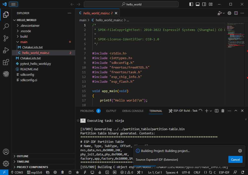
- During this process, the ESP-IDF may take up a lot of CPU resources, so it may cause the system to lag.
- If it is the first time to burn the program for a new project, you will need to select the download method, and select UART.
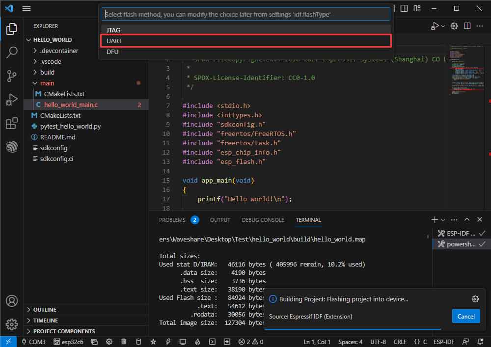
- This can also be changed later in the Download Methods section (click on it to bring up the options).
- As it comes with the onboard automatic download circuit, there is no need for manual operation to download automatically.
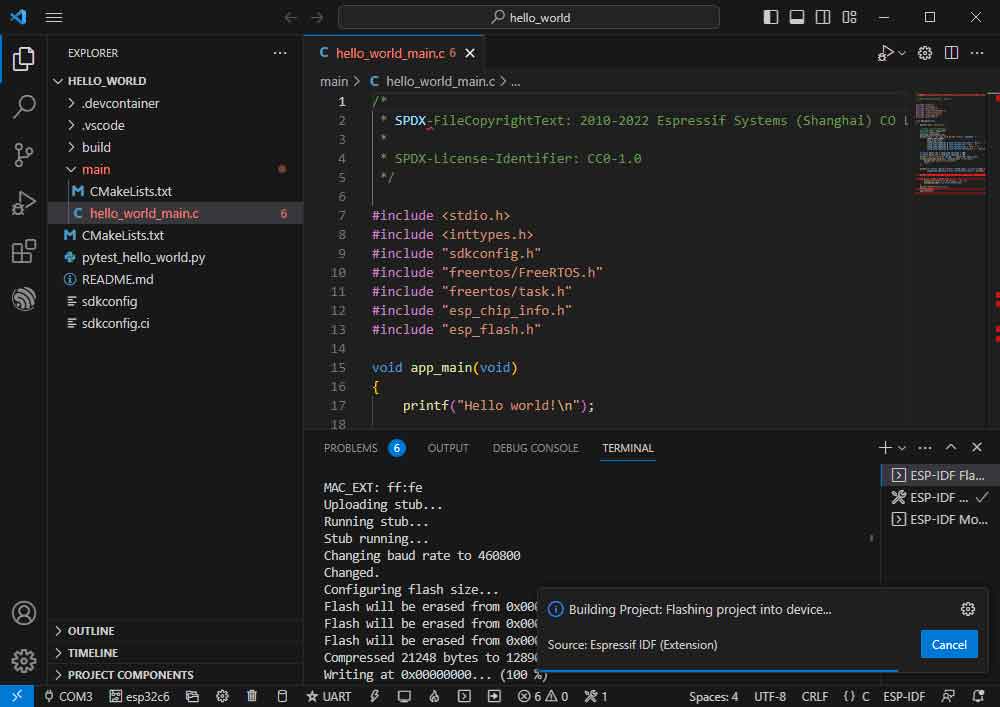
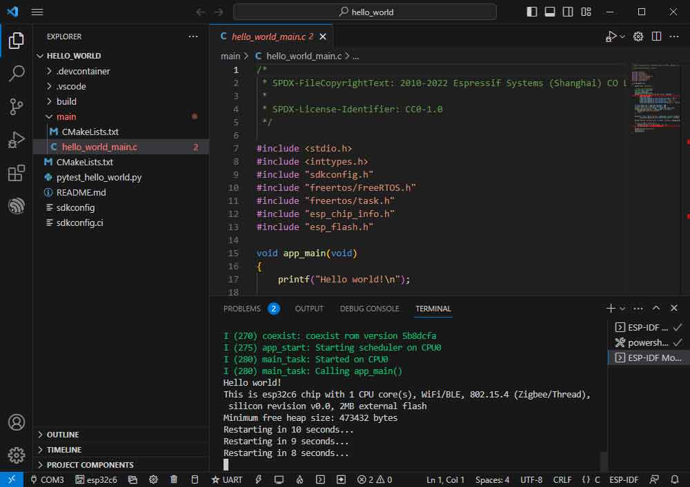
- After successful download, automatically enter the serial monitor, you can see the chip output the corresponding information and be prompted to restart after 10S.
Demo Example
Hello World
The official example path: get-started -> hello_world.
The example effect: Output Hello World! on the TERMINAL window every 10s.
Software Operation
- Create the official example "hello_world" according to the above tutorial. (Create Example)
- The demo is compatible with ESP32-C6. and you can directly use it no need to modify the demo.
- Modify the COM port and the driver object ( it is recommended to prioritize the use of USB corresponding to the COM port, can be viewed through the device manager), click on the compile and burn to run the demo.

GPIO
Official path: peripherals -> gpio -> generic_gpio.
Sample effect: LED blinks at 1-second intervals.
Hardware Connection
ESP32-C6 LED GPIO18(or GPIO19) LED+ GND LED-
Software Operation
- Follow the tutorial above to create the official example generic_gpio.
- The demo is compatible with ESP32-C6 and can be used without modifying the demo content.
- Modify the COM port and the driver object (it is recommended to use the COM port corresponding to USB first, you can check it through the device manager), click compile and burn to run the demo.
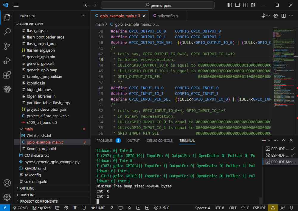
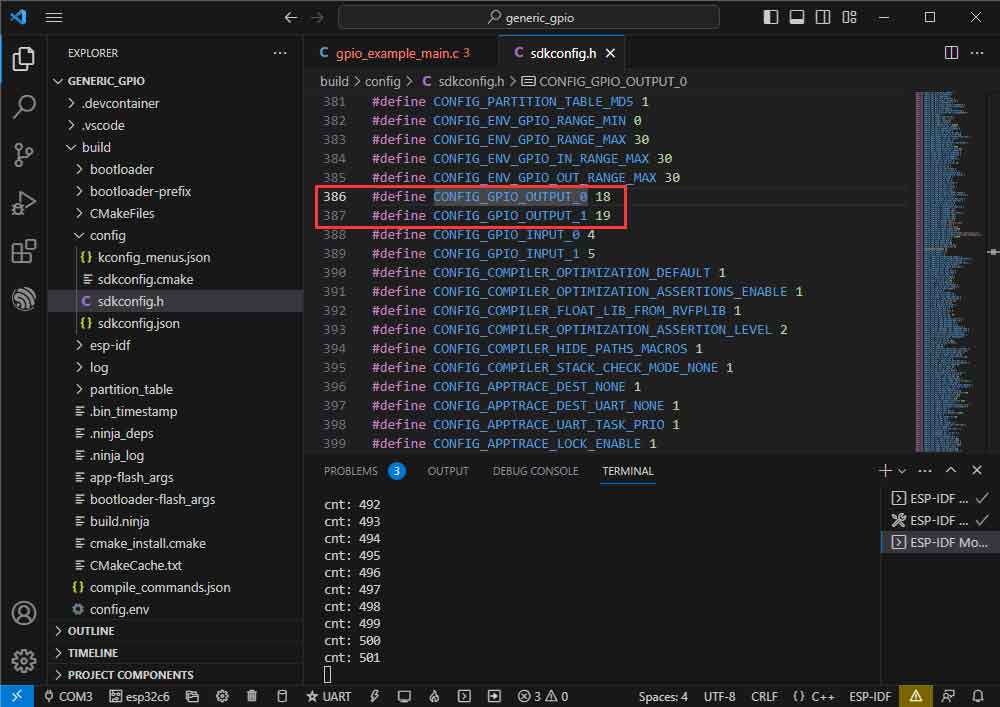
- Go to the demo macro definition location to see what GPIOs are actually handled.
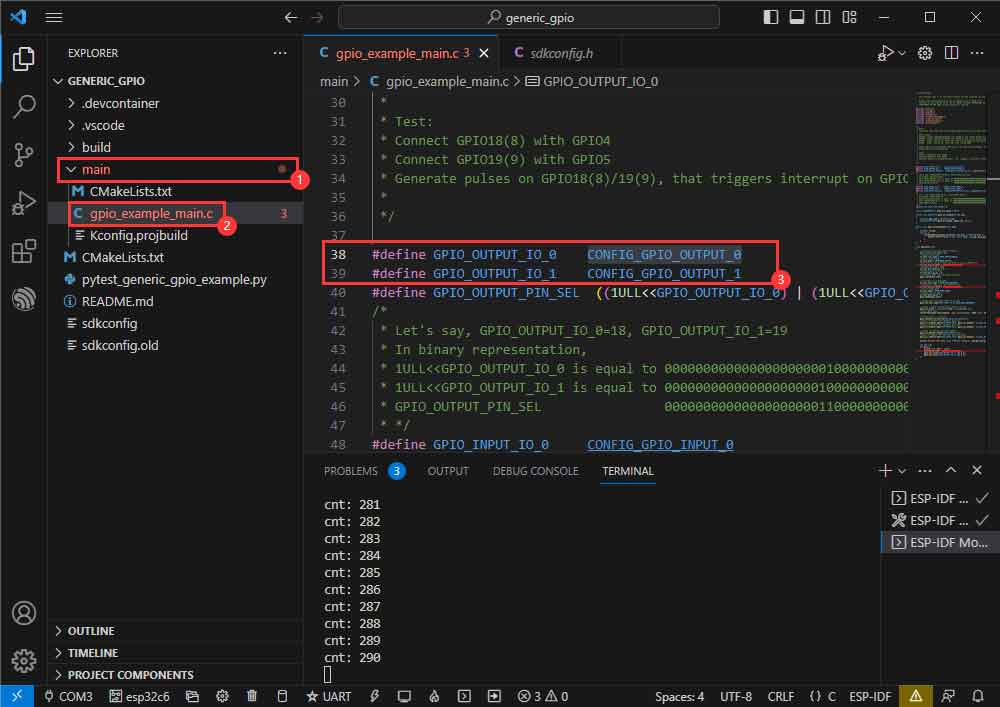
- Right-click and go to the GPIO definition location.
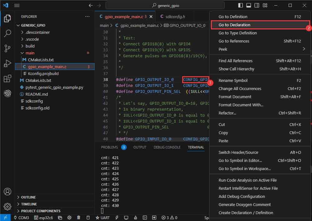
- The actual GPIOs are GPIO18, GPIO19.
RGB
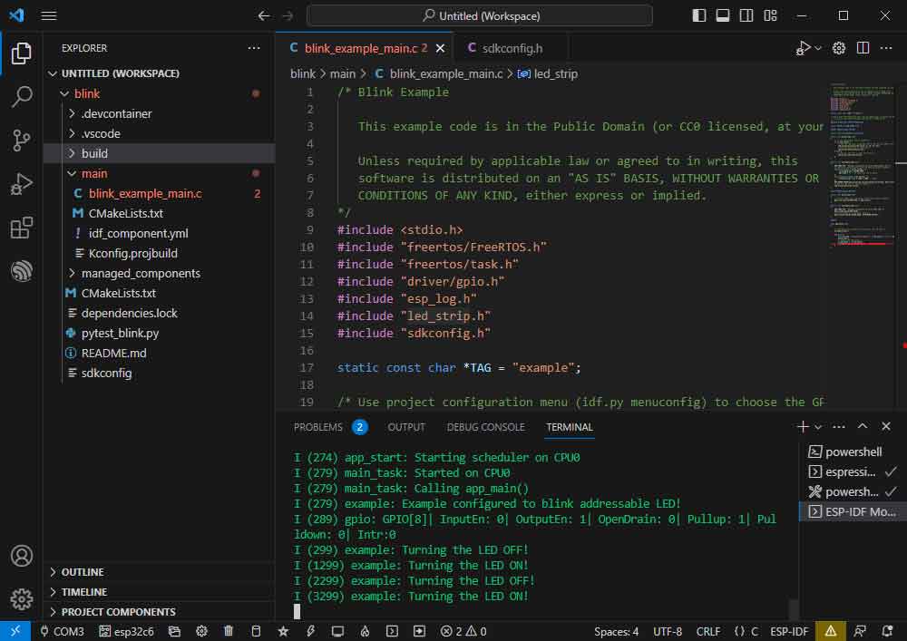
Official example path: get-started -> blink.
Sample effect: onboard RGB beads blink at 1-second intervals.
Software Operation
- Follow the tutorial above to create the official example blink. (Create Example)
- The demo is compatible with ESP32-C6 and can be used without modifying the demo content.
- Modify the COM port and the driver object (it is recommended to prioritize the COM port corresponding to USB, which can be viewed through the device manager), click compile, and burn to run the demo.
UART
Official example path: peripherals -> uart-> uart_async_rxtxtasks
Example effect: shorting GPIO4 and GPIO5 to send/receive UART data.
Hardware Connection
ESP32-C6 ESP32-C6 (the same one) GPIO4 GPIO5
Software Operation
- Create the official example uart_async_rxtxtasks according to the tutorial above. (Create Example)
- The demo is compatible with ESP32-C6 and can be used without modifying the demo content.
- Modify the COM port and driver object (it is recommended to prioritize the COM port corresponding to USB, which can be viewed through the device manager), click compile, and burn to run the demo.
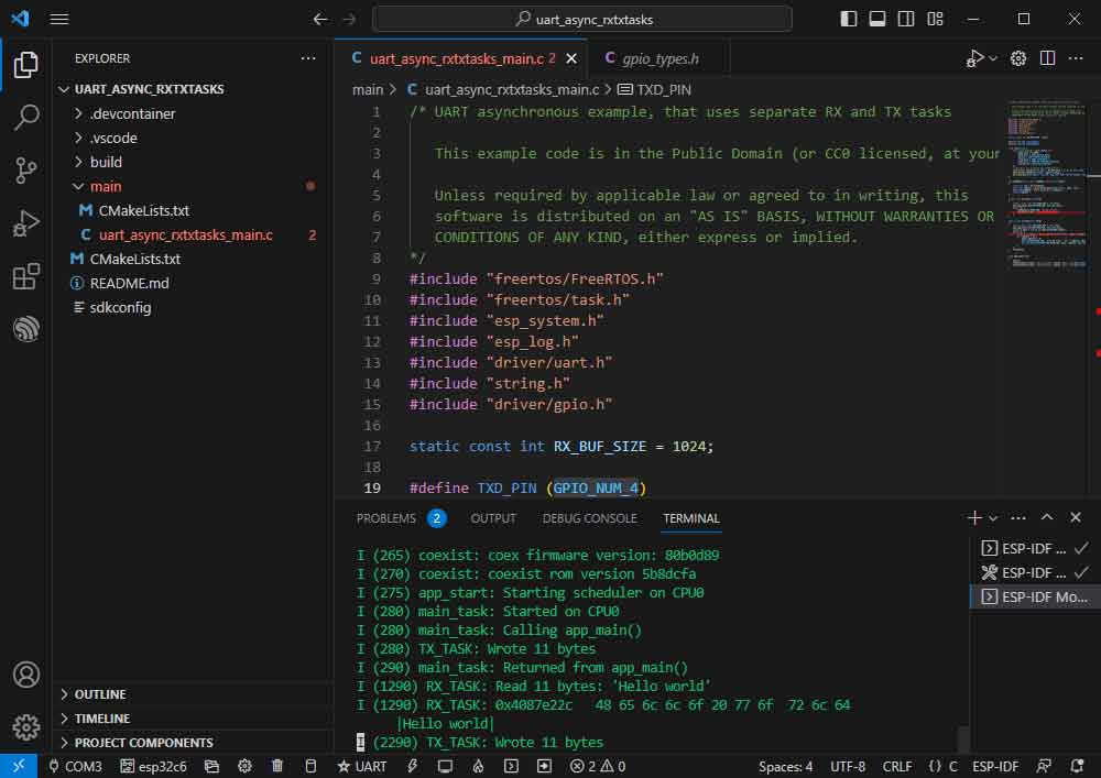
- Hardware connection according to the GPIO used.
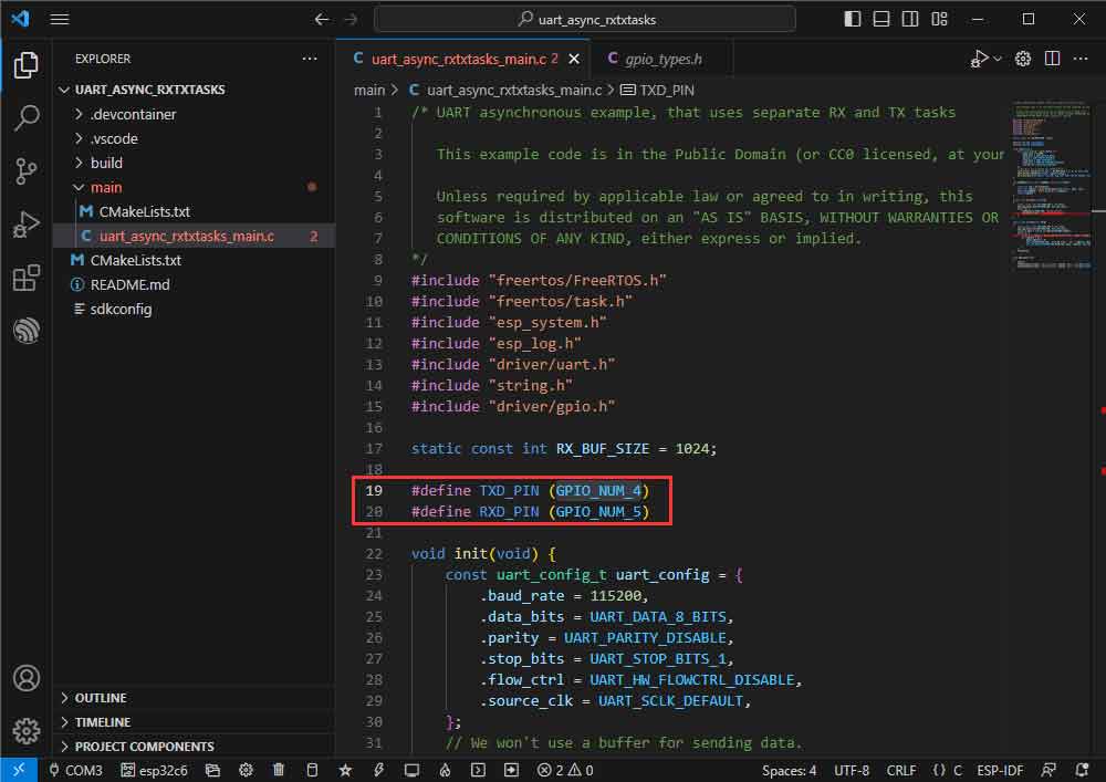
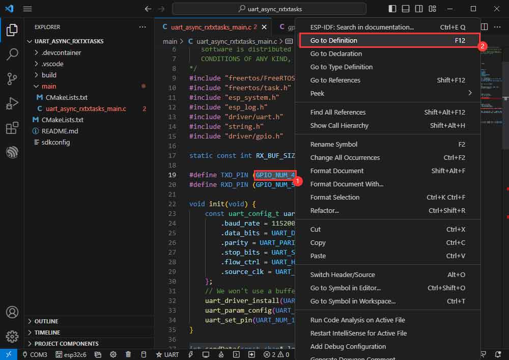
- You can go to the definition file to see the actual GPIOs used (check GPIO_NUM_4 -> Right click -> Go to Definition).
I2C
The official example path: peripherals -> lcd-> i2c_oled.
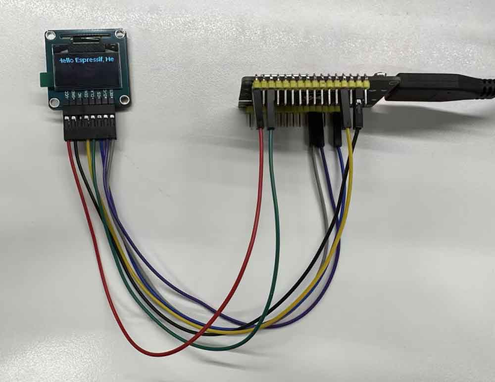
Example effect: turns on the 0.96-inch OLED (A) and displays a character.
Hardware Connection
| 0.96inch OLED (A) | ESP32-C6 |
| VCC | 3V3 |
| GND | GND |
| DIN | GPIO3 |
| CLK | GPIO4 |
| CS | GND |
| D/C | GND |
| RES | GPIO9 |
Software Operation
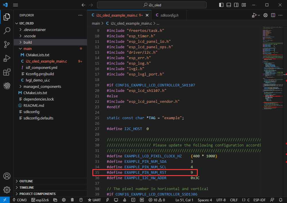
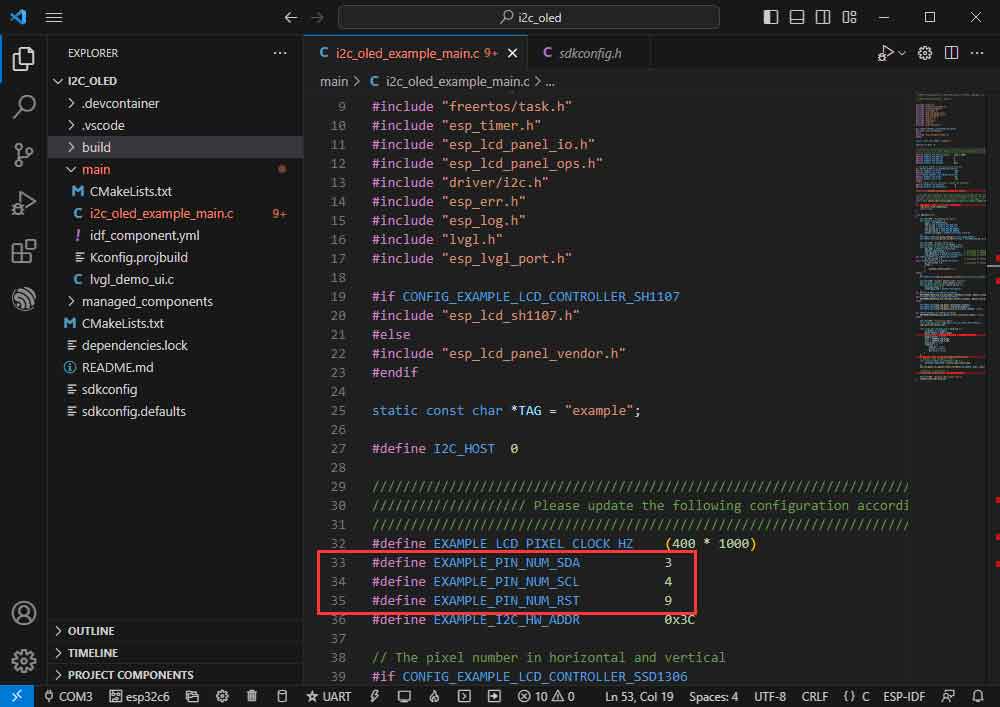
- Create the official example i2c_oled according to the tutorial above. (Create Example)
- Modify the demo to be compatible with 0.96-inch OLED (A).

- Adapts to 0.96-inch OLED (A), defines RES pin as GPIO9.
- Modify the COM port and the driver object ( it is recommended to prioritize the use of USB corresponding to the COM port, can be viewed through the device manager), click on the compile and burn to run the demo.
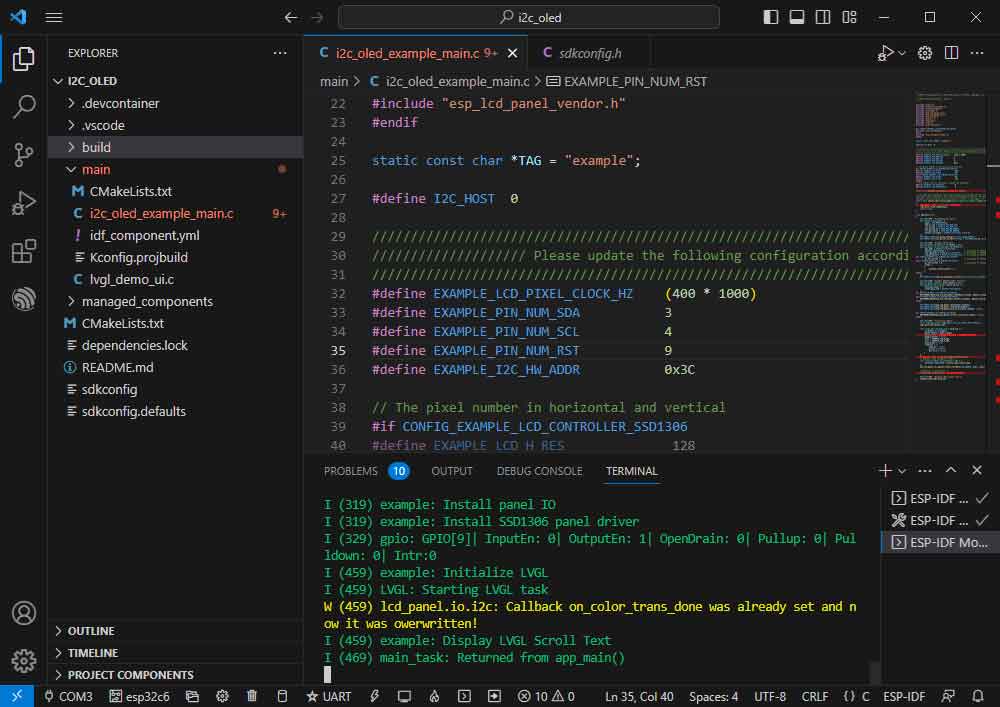
- The effect is as shown below:
- You can view the actual use of GPIO:
SPI
The path of the official example: peripherals -> spi_master-> lcd.
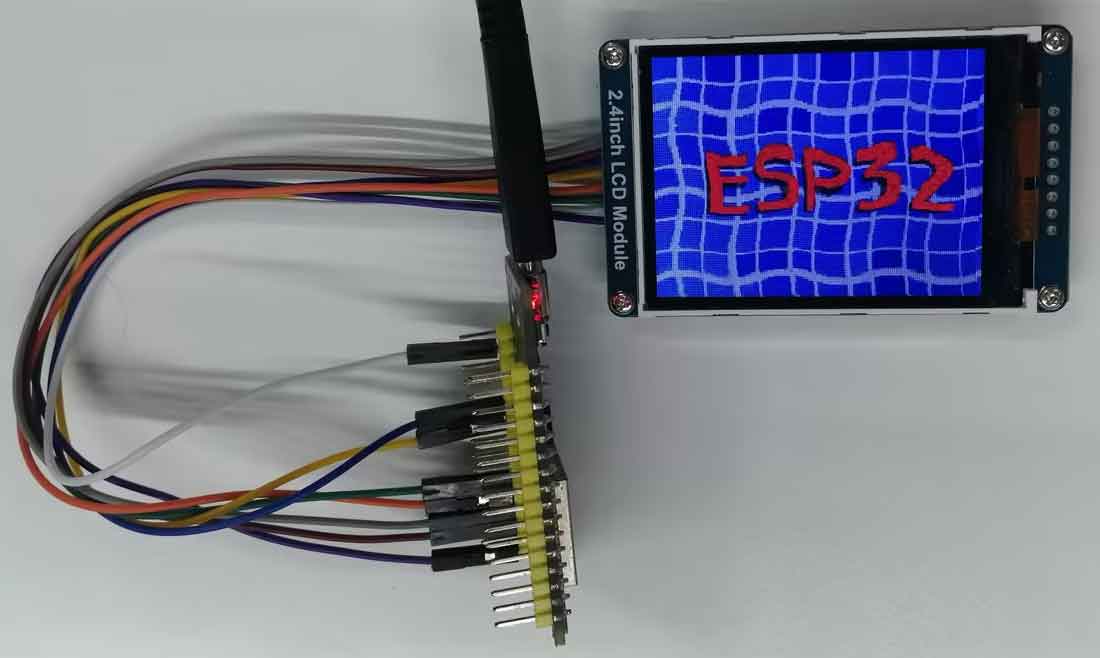
The example effect: dynamic displaying picture effect on the 2.4inch LCD Module.
Hardware Connection
| 2.4inch LCD Module | ESP32-C6 |
| VCC | 3V3 |
| GND | GND |
| DIN | GPIO7 |
| CLK | GPIO6 |
| CS | GPIO10 |
| D/C | GPIO11 |
| RES | GPIO4 |
| BL | GPIO5 |
Software Operation
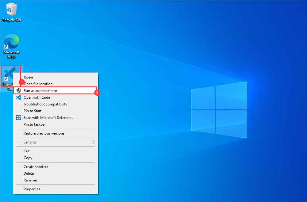
- Right-click on the VScode icon and run VScode as administrator:
- Create an official LCD example according to the tutorial above.
Modify the program to make it compatible with a 2.4inch LCD Module.
- Jump to a defined position.
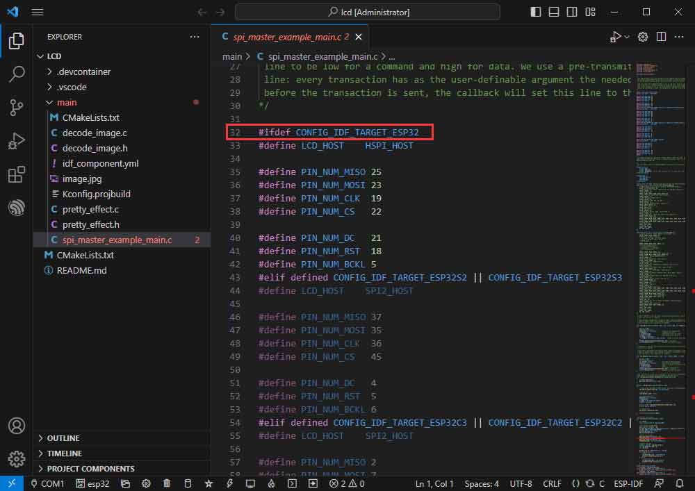
- Currently using ESP32-C6, shielding other chip definitions.
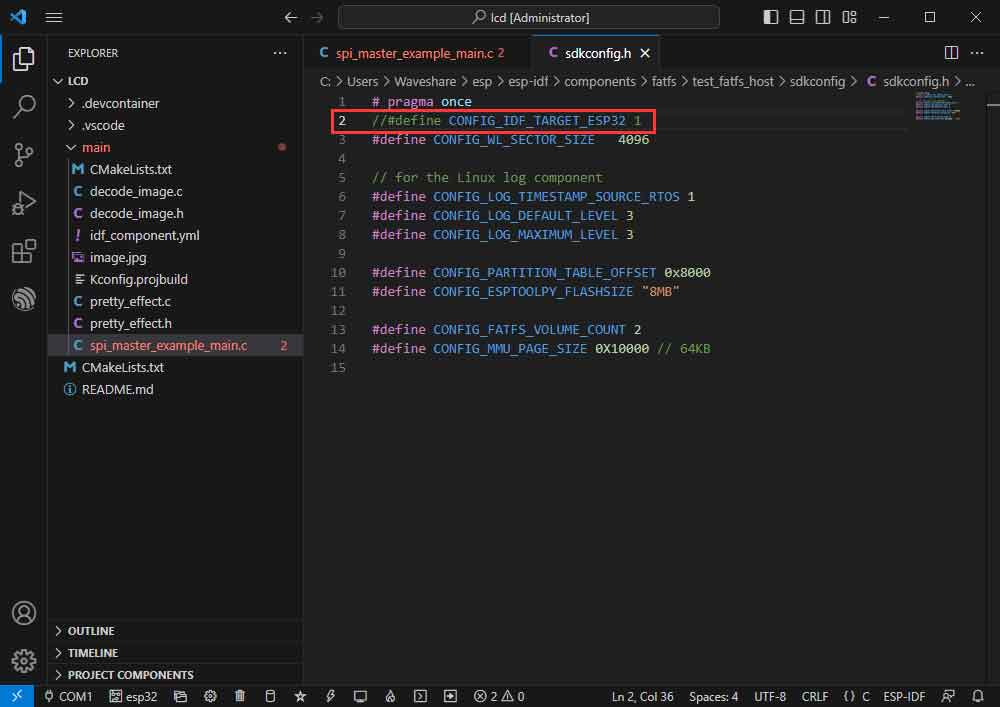
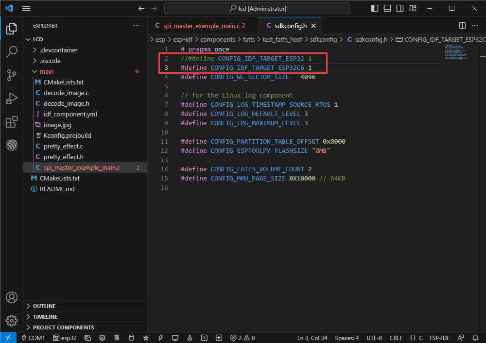
- And macro-define ESP32-C6, CONFIG_IDF_TARGET_ESP32C6.
//#define CONFIG_IDF_TARGET_ESP32 1
#define CONFIG_IDF_TARGET_ESP32C6 1
- Modify D/C using IO.
- Enter the 62 line of spi_master_example_main.c.
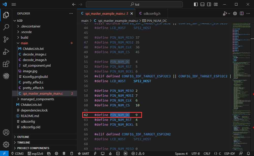
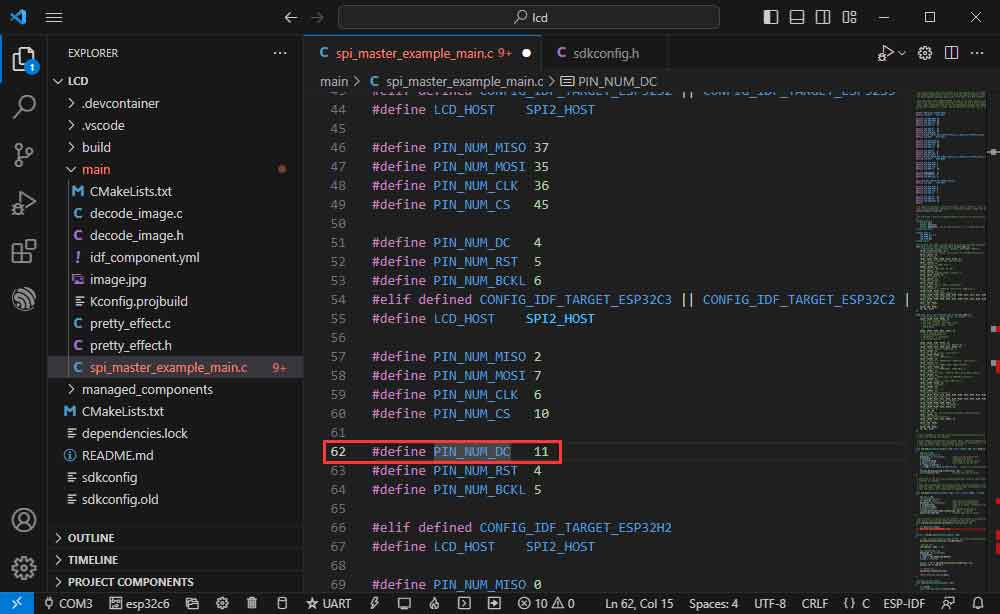
- Modify the D/C to use IOs to avoid the download circuit (GPIO11 instead of GPIO9).
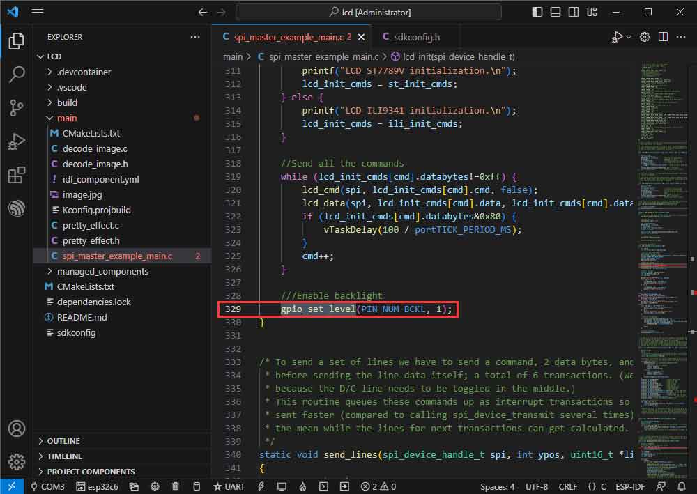
- Modify the backlight:
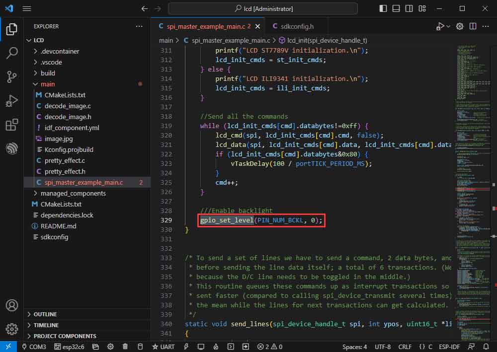
- Modify it as gpio_set_level(PIN_NUM_BCKL, 1);
- Modify the COM port and the driver object (it is recommended to prioritize the use of USB corresponding to the COM port, can be viewed through the device manager), click on the compile and burn to run the demo.
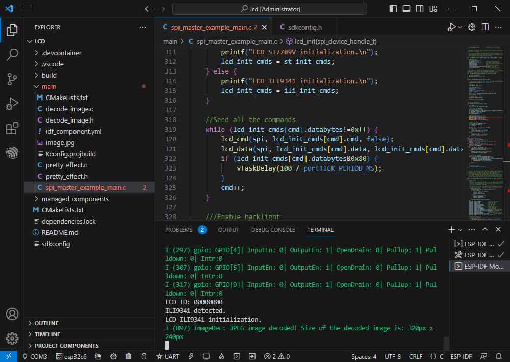
- The effect is as shown below:
Bluetooth
Official sample path: Bluetooth -> bluedroid -> ble -> gatt_server.
Example effect: ESP32-C6 and cell phone Bluetooth debugging assistant for data transmission.
Software Operation
- Install the Bluetooth debugging assistant on your phone.
- Follow the tutorial above to create the official example gatt_server.
- The demo is compatible with ESP32-C6 and can be used without modifying the demo content.
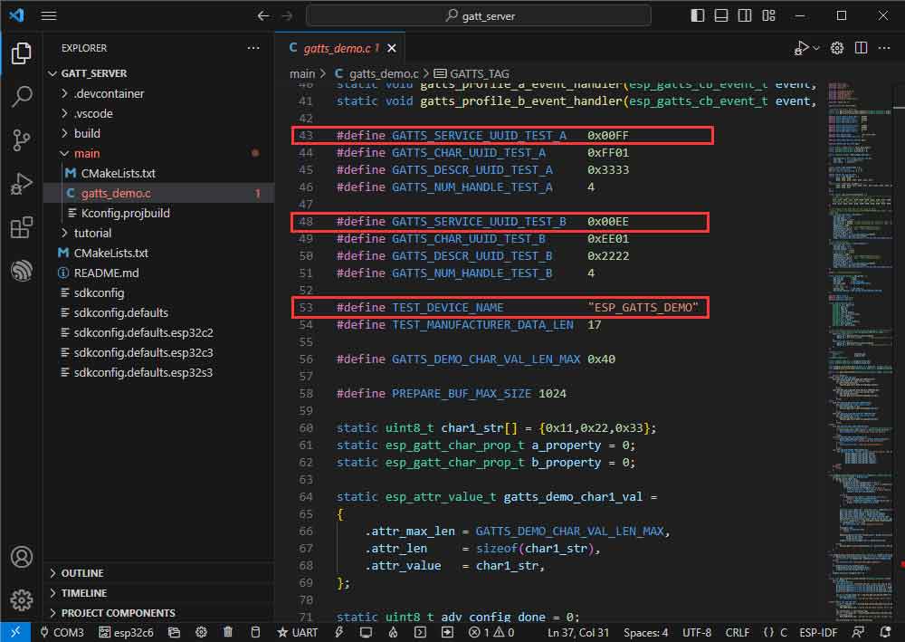
- Bluetooth name and UUID, Bluetooth name is ESP_GATTS_DEMO.
- Modify the COM port and the driver object (it is recommended to prioritize the use of USB corresponding to the COM port, which can be viewed through the device manager), click on the compile, and burn to run the demo.
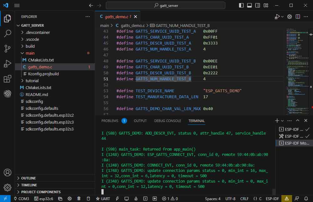
- Connecting the ESP_GATTS_DEMO Bluetooth device on the phone.
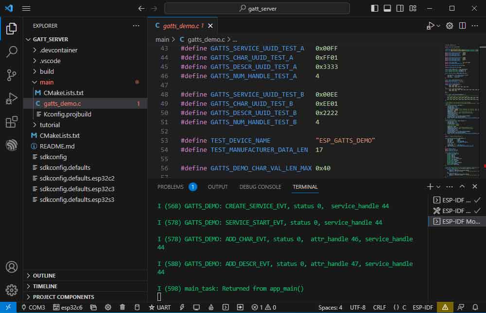
- The effect of a successful connection is shown below:
- Based on the UUID value in the demo, select one of the two servers for upstream transmission.
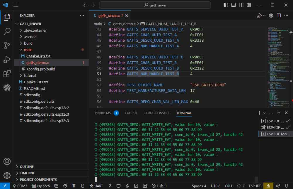
- The ESP32-C6 receives data:
WIFI
Official example path: wifi-> getting_started-> station.
Sample effect: ESP32-C6 connects to WIFI.
Software Operation
- Create the official example station according to the tutorial above.
- Modify the contents of the demo to connect to the required WiFi.
- Go to the Kconfig.projbuild file.
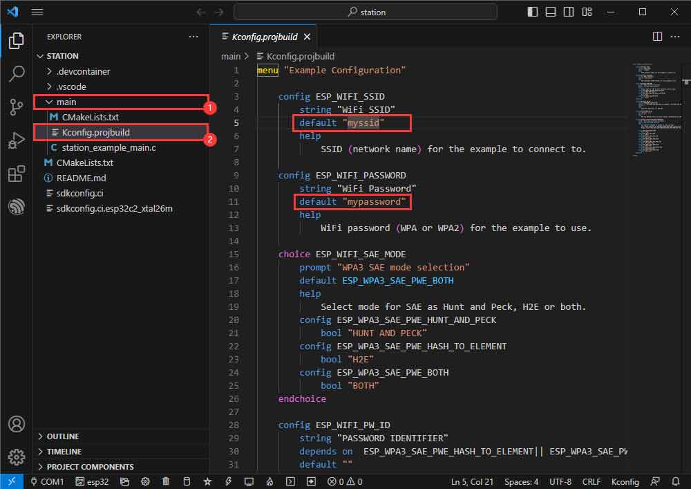
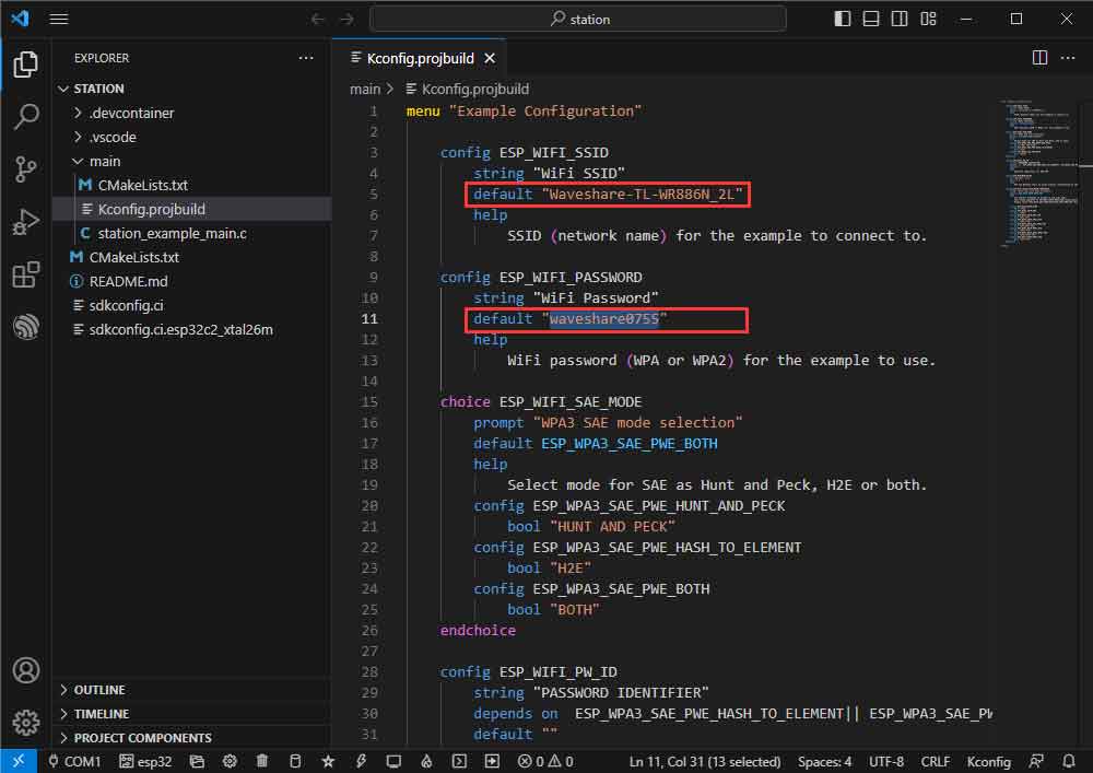
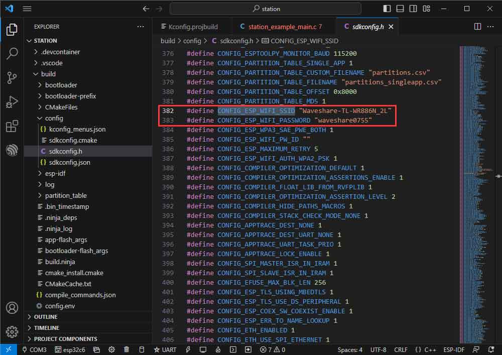
- Change the original WiFi SSID and WiFi Password to the WiFi information you want to connect to.
- Modify the COM port and the driver object ( it is recommended to prioritize the use of USB corresponding to the COM port, which can be viewed through the device manager), click on the compile, and burn to run the demo.
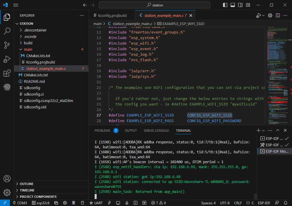
- You can check the value of CONFIG_ESP_WIFI_SSID.
- Go to the station_ example_ main.c file.
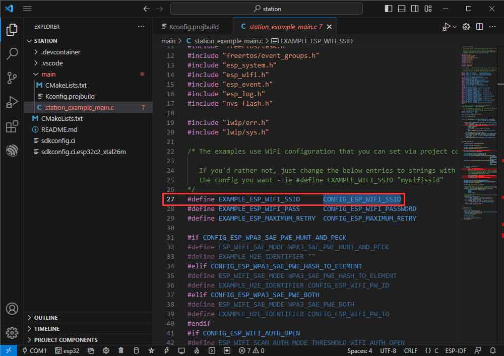
- Right-click to go to the definition.
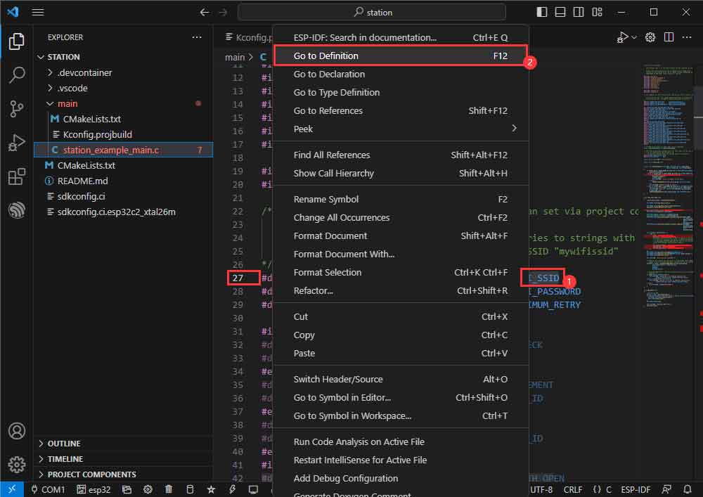
- The previously set value can be seen as:
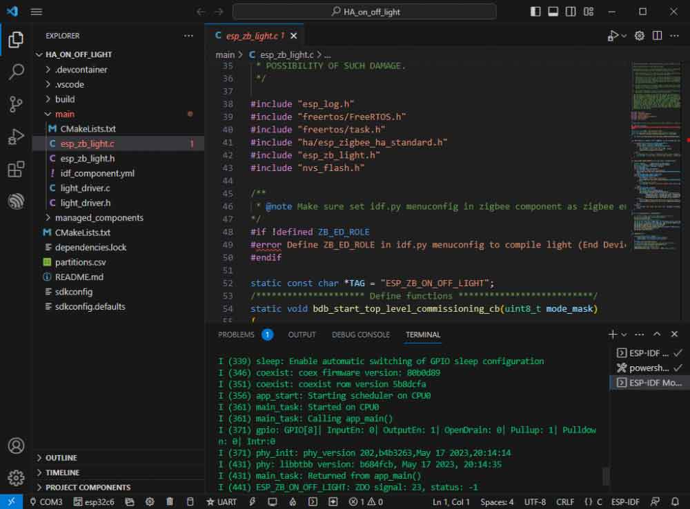
Zigbee
- Official example 1 path: Zigbee -> light_sample -> HA_on_off_switch.
- Official example 2 path: Zigbee -> light_sample -> HA_on_off_light.
- Example effect: two ESP32-C6, use the BOOT button of one of them (burn HA_on_off_switch demo) to control the RGB light beads of the other one.
- Note: Please burn the HA_on_off_switch demo to one piece first, and then burn the HA_on_off_light program to the other piece.
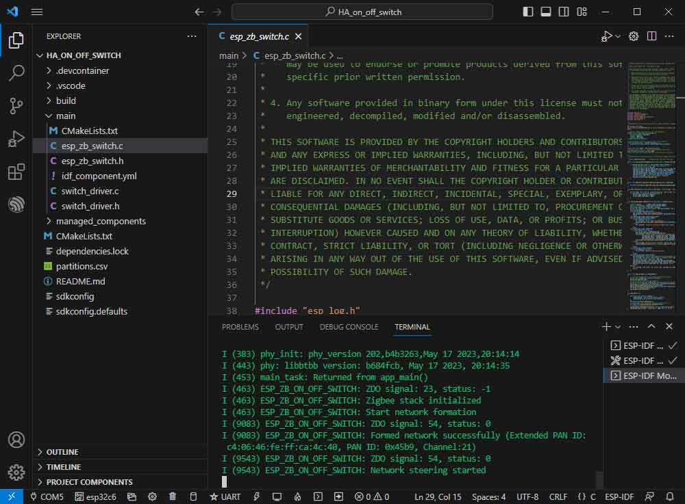
Software Operation 1
- Create the official example HA_on_off_switch according to the tutorial above.
- The demo is compatible with ESP32-C6 and can be used without modifying the demo content.
- Modify the COM port and the driver object (it is recommended to use the COM port corresponding to USB in preference, which can be viewed through the device manager), click compile, and burn to run the demo.
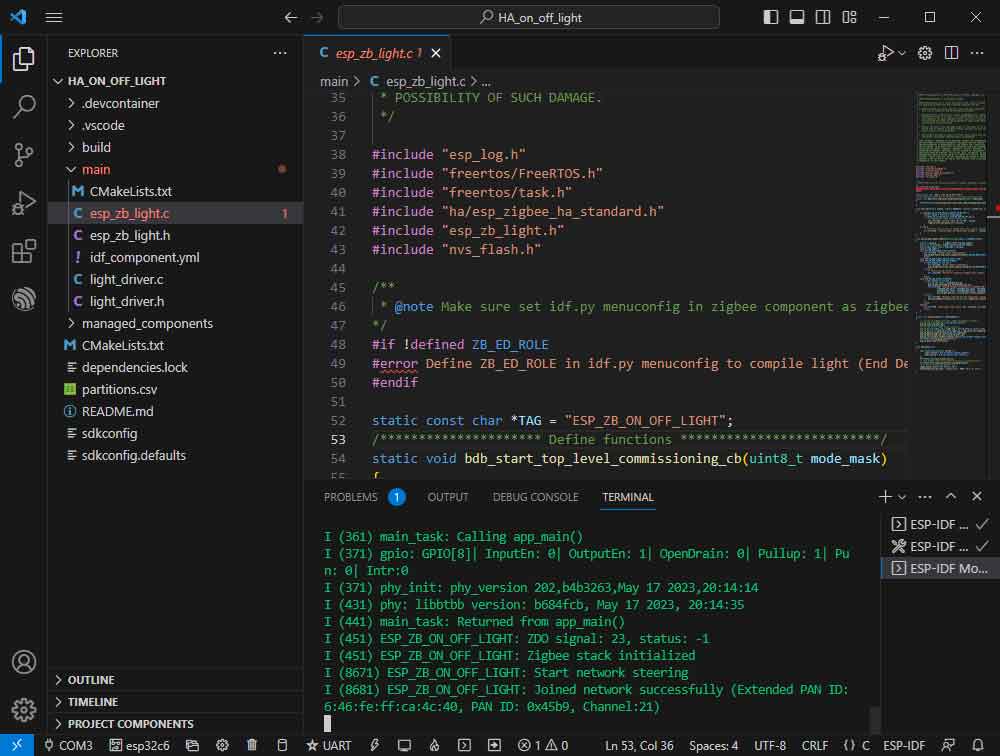
Software Operation 2
- Follow the tutorial above to create the official example HA_on_off_light.
- The demo is compatible with ESP32-C6 and can be used without modifying the demo content.
- Modify the COM port and driver object, click compile and burn to run the demo (you need to wait for a moment for the two chips to establish a connection).
- If the device remains unconnected, it may be due to residual network information on the device, so you can erase the device information (Erase Tutorial) and reorganize the network.
JTAG Debug
Software Operation
- Create a debugging example, this example uses the official example hello_world.
- Modify the launch.json file.
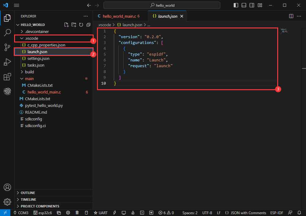
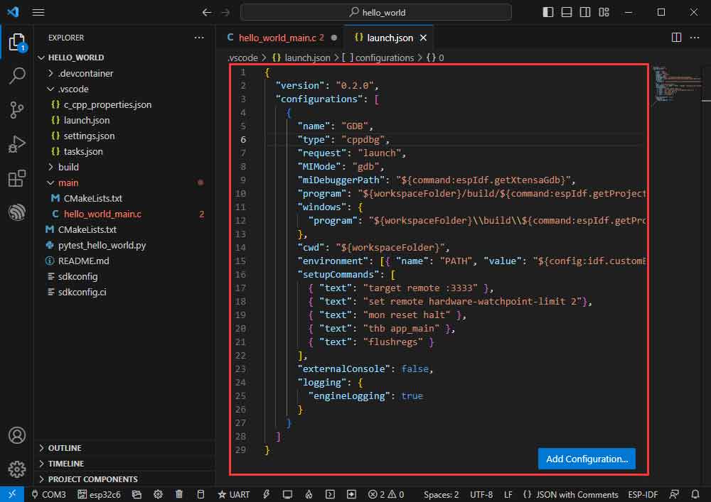
- Input the following content:
{
 "version": "0.2.0",
 "configurations": [
   {
     "name": "GDB",
     "type": "cppdbg",
     "request": "launch",
     "MIMode": "gdb",
     "miDebuggerPath": "${command:espIdf.getXtensaGdb}",
     "program": "${workspaceFolder}/build/${command:espIdf.getProjectName}.elf",
     "windows": {
       "program": "${workspaceFolder}\\build\\${command:espIdf.getProjectName}.elf"
     },
     "cwd": "${workspaceFolder}",
     "environment": [{ "name": "PATH", "value": "${config:idf.customExtraPaths}" }],
     "setupCommands": [
       { "text": "target remote :3333" },
       { "text": "set remote hardware-watchpoint-limit 2"},
       { "text": "mon reset halt" },
       { "text": "thb app_main" },
       { "text": "flushregs" }
     ],
     "externalConsole": false,
     "logging": {
       "engineLogging": true
     }
   }
 ]
}
- The demo is compatible with ESP32-C6 and can be used without modifying the demo content.
- Modify the COM port and the driver object (Please use the USB interface; the UART interface does not support JTAG debugging. The corresponding COM port can be checked through the Device Manager.), click compile, and burn to run the demo.

- Press F1 and input:
ESP-IDF:Device configuration
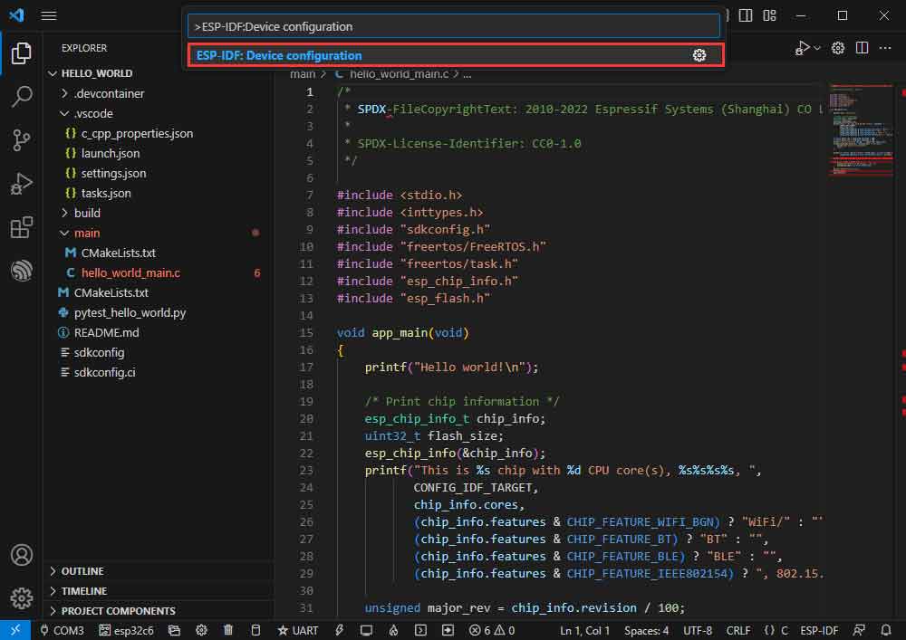
- Select OpenOcd Config Files.
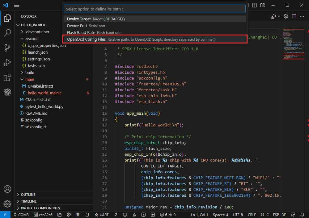
- Type board/esp32c6-builtin.cfg (if this is the default, just enter)
board/esp32c6-builtin.cfg

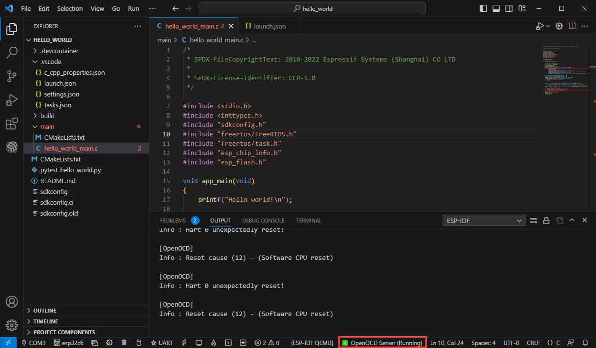
- Stretch the width of the window until [OpenOCD Server] is displayed at the bottom.

- Click [OpenOCD Server] and select Start OpenOCD.

- Successfully opened as follows:
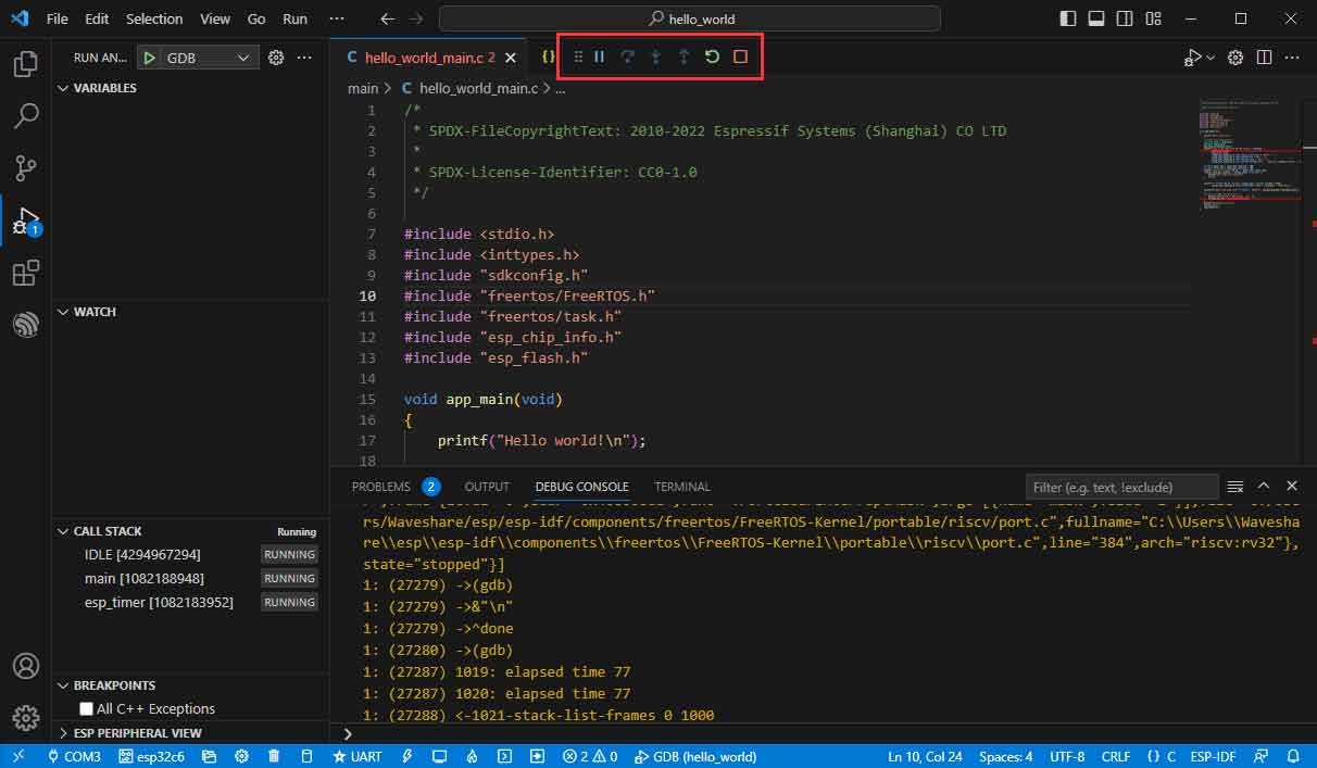
- Go to the debug function and click Debug:
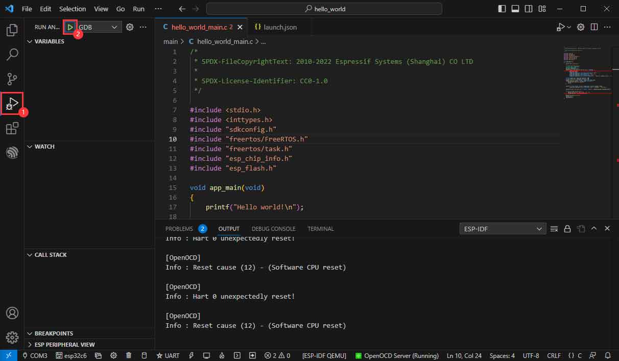
- Successfully enter the debugging interface:
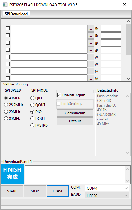
Erase Device Flash
- Unpack the software resource package (Flash debugging software).
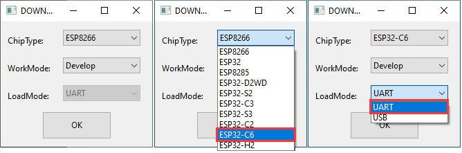
- Open flash_download_tool_3.9.5.exe software, select ESP32-C6 and UART.
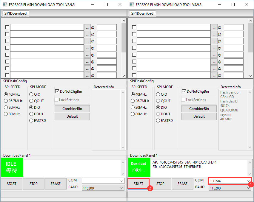
- Select the UART port number, and click Start (not select any bin file).
- After programming, click on "ERASE".
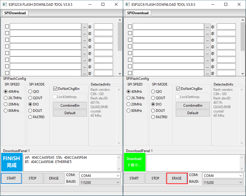
- Waiting for Erase to Finish.