- sales/support
Google Chat: zj734465502@gmail.com
- sales
+86-0755-88291180
- sales01
sales01@spotpear.com
- sales02
dragon_manager@163.com
- support
services01@spotpear.com
- CEO-Complaints
manager01@spotpear.com
- sales/support
WhatsApp:13246739196
- HOME
- >
- PRODUCTS
- >
- For Arduino
- >
- Mother Board

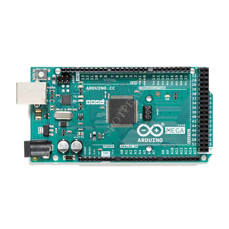
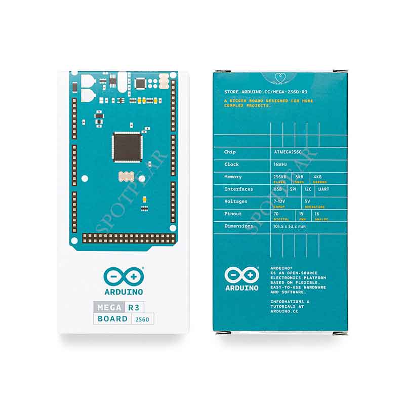
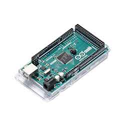
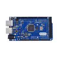
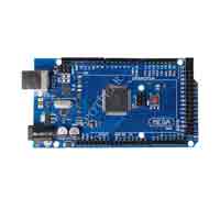
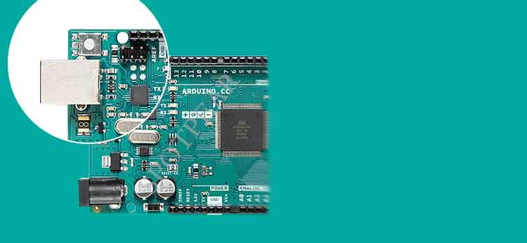
Official Original MEGA2560 R3 development board for Arduino MEGA2560 R3
$55.9
Official Original MEGA2560 R3 development board for Arduino MEGA2560 R3
For Arduino Recommend
Official Arduino Board Recomme
【Overview】
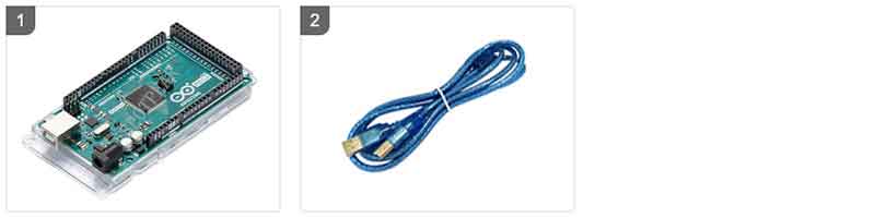
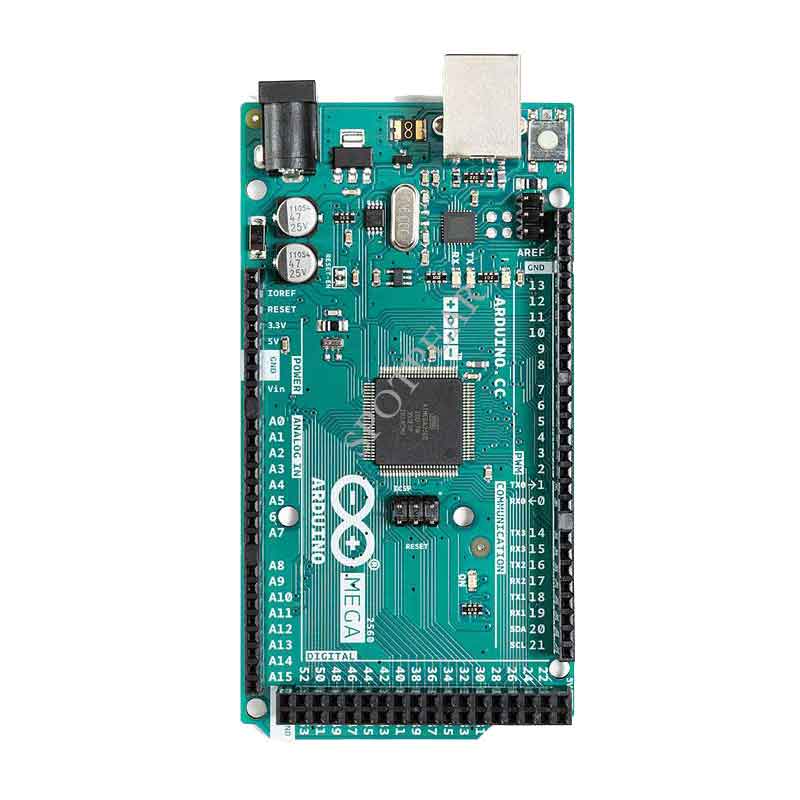
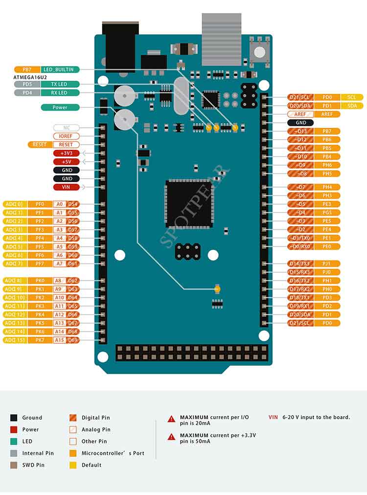
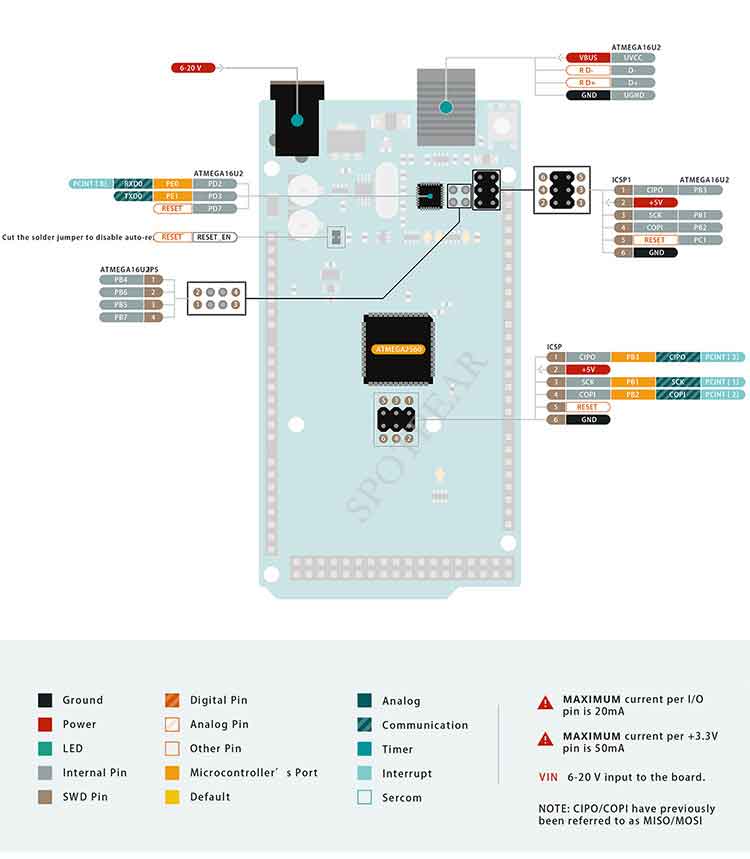
[] The Arduino Mega2560 R3 is a microcontroller board based on the ATmega2560. It has 54 digital input/output pins (of which 14 can be used as PWM outputs), 16 analog inputs, 4 UARTs (hardware serial ports), a 16 MHz crystal oscillator, a USB connection, a power jack, an ICSP header, and a reset button. It contains everything needed to support the microcontroller; simply connect it to a computer with a USB cable or power it with a AC-to-DC adapter or battery to get started.
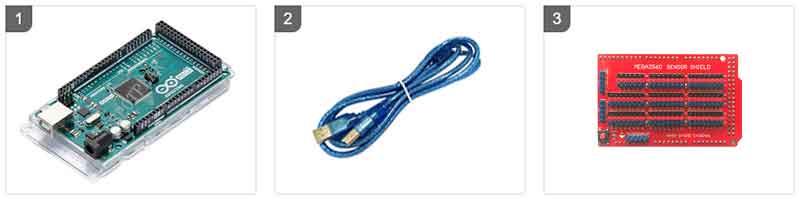
[] The Mega 2560 board is compatible with most shields designed for the Uno and the former boards Duemilanove or Diecimila.
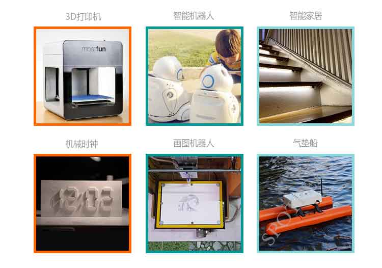
[] Compared to other models of Arduino controllers, Arduinomega2560R3 has a larger computational storage space and is widely used in fields such as 3D printers, plotting robots, smart robots, and smart homes.
[] Compared to the previous two versions, it has the following new features:
1. Two additional pins, SDA and SCL, have been added at AREF to support the I2C interface. IOREF and one reserved pin have also been added.
2. The reset circuit design has been improved.
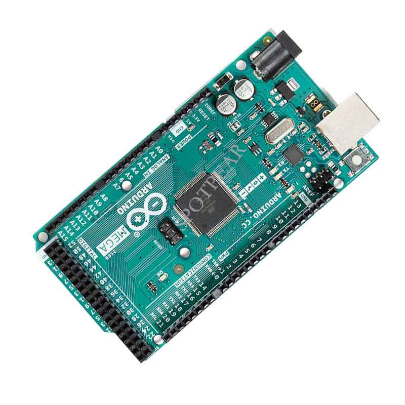
3. The USB interface chip has been replaced with ATmega16U2 instead of ATmega8U2.
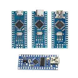
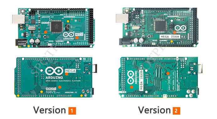
【Comparison of different versions】
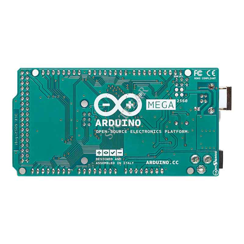
[] There are differences in the silkscreen markings on the front and back sides, but there are no other changes that affect usability. Random shipment will be made.
【Specifications】
[] Microcontroller: ATmega2560
[] Operating Voltage: 5V
[] EEPROM: 4KB
[] Flash Memory: 256KB (8KB used for the bootloader)
[] SRAM: 8KB
[] Frequency: 16MHz
[] Input Voltage (Recommended): 7-9V
[] DC Current per I/O Pin: 40mA
[] DC Current for 3.3V Pin: 50mA
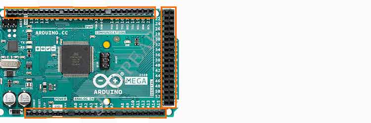
[] Digital I/O Pins: 54 (including 14 PWM output pins)
[] Analog Input Pins: 16
[] Dimensions: 101.52*53.3mm
[] Weight: 37g
【Function introduction】
[] Power Supply
The Arduino Mega can be powered either through a USB cable or an external power source. When both are connected simultaneously, the board automatically selects the power source. The external power can come from an AC-to-DC power adapter or a battery, connected through the DC power jack on the board. If the external power is below 7V, the 5V output pin may provide less than 5V, and the board may operate unstably. If the external power exceeds 9V, the voltage regulator chip may overheat and damage the board. The recommended voltage range is 7-9V.
[] In-out
With the use of the pinMode(), digitalWrite(), and digitalRead() functions, each of the 54 digital I/O pins on the Arduino Mega can be configured as an input or output. Each pin has an internal pull-up resistor of 20-50 kilohms (disabled by default) and can handle a maximum current of 40mA when used for output.
[] USB overcurrent protection
The Arduino Mega features a self-resetting polyfuse to protect the USB port of your computer from short circuits or overcurrent. While most computers provide internal protection, the polyfuse offers an additional safeguard. If the current exceeds 500mA, the polyfuse automatically disconnects to prevent short circuits or overloads.
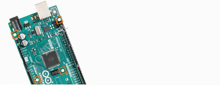
[] Physical characteristics
The PCB dimensions of the Arduino Mega are 4x2.1 inches, with the USB interface and power jack extending beyond this size. Four mounting holes are provided to secure the board to other surfaces or enclosures. It's important to note that the spacing between digital pins 7 and 8 is 160mil (0.16"), which is different from the standard 100mil spacing of other pins.
The Mega 2560 is compatible with most extension boards designed for the UNO, Diecimila, or Duemila-nove. The digital pins 0-13 (including adjacent AREF and GND pins), analog inputs 0-5, power interface, and ICSP interface are all located in the same positions. Additionally, the primary serial port is also in the same location on pins 0 and 1, along with external interrupts 0 and 1 (pins 2 and 3). The SPI interface is accessed through the ICSP pins. It's important to note that the I2C pins are on pins 20 and 21 of the Mega, unlike the analog pins 4 and 5 on the Diecimila or Duemilanove.
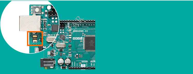
[] Automatic reset
When the Arduino Mega is connected to a computer, you can establish a connection and control the main controller's reset function through software, eliminating the need to manually press the reset button on the board. The DTR (Data Terminal Ready) pin on the ATmega16U2 is connected to the reset pin of the ATmega2560 using a 100nF capacitor. When the DTR is triggered (pulled low), it pulls the reset button low for a sufficient duration to reset the chip. The Arduino software utilizes this feature, allowing you to simply click the upload button in the software to download the program. This means that the bootloader has a brief timeout, and the DTR signal coordinates well to provide the reset pulse after the download begins.
This setup also has implications when the Mega is connected to other systems like macOS or Linux. Each time the software reset connection is made, after approximately half a second, the Mega2560 will run the bootloader. It will ignore any erroneous data during programming and intercept the first few bytes of data sent to the board once the connection is open. If a program is running on the board, it will retrieve the configuration and other data when it starts running, ensuring that the software waiting to communicate before sending data waits for one second after opening the connection. The UNO also has a jumper for disabling the auto-reset feature. It is labeled "RESET-EN" on the silkscreen, and cutting the trace between the two solder pads disables the auto-reset function. Alternatively, you can connect a 110-ohm resistor between 5V and the reset pin to disable the auto-reset feature.
[] Communication
The Arduino Mega offers a range of tools for communication with a computer, other Arduinos, or other main controllers. The Mega provides 4 hardware serial ports for TTL-level communication. The ATmega16U2 also allows for virtual serial (CDC) communication on the computer via USB, using a standard USB serial driver (an .inf file may be required on Windows). The 16U2 firmware utilizes the standard USB serial port driver and does not require additional drivers. The Arduino software also includes a Serial Monitor, which allows for simple data transmission and reception between the Arduino board and the computer. When data is being transmitted via USB, the RX and TX LEDs on the board will blink (note that this feature does not apply to the 0 and 1 ports).
Additionally, a software simulated serial library is available that enables serial communication using other digital ports on the Mega2560. The ATmega2560 also supports I2C (TWI) and SPI communication, and the Arduino software includes the Wire library for TWI (I2C) communication. If SPI communication is needed, the SPI library can be used.
[] Program
The Arduino MEGA can be programmed using the Arduino software.
The ATmega2560 chip on the Arduino MEGA is pre-programmed with a bootloader, which allows you to upload new programs to the board without the need for an external hardware programmer. The bootloader uses the STK500 protocol for communication.
You can also bypass the bootloader and use an external programmer to burn programs onto the ATmega2560 chip through the ICSP (In-Circuit Serial Programming) pins.
[] Memory
The ATmega2560 has 256 KB of flash memory for storing code (of which 8 KB is used for the bootloader), 8 KB of SRAM and 4 KB of EEPROM (which can be read and written with the EEPROM library).
【Application Examples】