- sales/support
Google Chat:---
- sales
+86-0755-88291180
- sales01
sales@spotpear.com
- sales02
dragon_manager@163.com
- support
tech-support@spotpear.com
- CEO-Complaints
zhoujie@spotpear.com
- Only Tech-Support
WhatsApp:13246739196
- Purchase/Shipping/Refund
WhatsApp:13424403025
RP2350-Zero-CM User Guide
Features
- Uses the RP2350A microcontroller chip developed by Raspberry Pi
- Unique dual-core, dual-architecture, featuring dual-core ARM Cortex-M33 processors and dual-core Hazard3 RISC-V processors, both operating at up to 150MHz, allowing users to flexibly switch between the two architectures
- Built-in 520KB of SRAM and 2MB of on-chip Flash
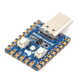
- Type-C male port design
- Supports Type-C power supply (compatible with PD protocol)
- Castellated module design allows direct soldering and integration onto custom base boards
- Supports USB 1.1 host and device modes
- Supports low-power sleep and dormant modes
- Drag-and-drop programming using mass storage over USB
- All 29 GPIO pins of the RP2350A are brought out (20 via pin headers, the rest accessible only via soldering)
- 2 SPI, 2 I2C, 2 UART, 4 12-bit ADC, and 16 controllable PWM channels
- Accurate on-chip clock and timer
- Built-in temperature sensor for real-time chip temperature monitoring
- 12 × programmable I/O (PIO) state machines for custom peripheral support
Onboard Resources

- RP2350A Dual-core, dual-architecture processor, up to 150MHz operating frequency
- 2MB NOR Flash Onboard 2MB NOR Flash memory
- Debug Interface For program debugging and development
- RP2350A Pins Brings out 10 pins (requires soldering), 9 of which are GPIO pins
- USB Type-C Male Port For programming, supports USB 1.1 host and device modes
- ME6217C33M5G Low dropout LDO, current (Max) 800mA
- BOOT button Press while resetting to enter download mode
- RUN Reset Button For resetting the board
- WS2812 Colorful RGB LED
Interface Introduction

Dimensions

Working with MicroPython
This chapter contains the following sections. Please read as needed:
MicroPython Getting Started Tutorials
New to Pico MicroPython development and want to get started quickly? We have prepared a general introductory tutorial for you. This tutorial is designed to help developers quickly become familiar with Thonny IDE and start developing. It covers environment setup, project creation, component usage, and peripheral programming, helping you take the first step in MicroPython programming.
- Section 1 Basic Introduction
- Section 2 GPIO
- Section 3 PWM
- Section 4 ADC
- Section 5 UART
- Section 6 I2C
- Section 7 SPI
- Section 8 PIO
Setting Up the Development Environment
Please refer to the Install and Configure Thonny IDE Tutorial to download and install the Thonny IDE.
Example
The MicroPython examples are located in the examples\MicroPython directory of the example package.
| Example | Basic Program Description | Dependency Library |
|---|---|---|
| 01_WS2812 | Onboard RGB LED example | - |
01_WS2812
Example Description
- Uses GPIO16 to drive a WS2812B RGB LED via PIO, cycling through colors.
Hardware Connection
- Connect the board to the computer using a USB cable.
Operation Result
- After flashing, the WS2812B RGB LED continuously fades through red, green, and blue.
Working with C/C++
This chapter contains the following sections. Please read as needed:
Setting Up the Development Environment
Please refer to the Install and Configure Pico C/C++ Development Environment Tutorial to download and install the Pico VS Code.
Example
The C/C++ examples are located in the examples\C directory of the example package.
| Example | Basic Program Description | Dependency Library |
|---|---|---|
| 01_WS2812 | Onboard RGB LED example | - |
01_WS2812
Example Description
- Uses GPIO16 to drive a WS2812B RGB LED via PIO, cycling through colors.
Hardware Connection
- Connect the board to the computer using a USB cable.
Operation Result
- After flashing, the WS2812B RGB LED continuously fades through red, green, and blue.
Working with Arduino
This chapter contains the following sections. Please read as needed:
Setting Up the Development Environment
Please refer to the Install and Configure Arduino IDE Tutorial to download and install the Arduino IDE.
Example
The Arduino examples are located in the examples\Arduino directory of the example package.
| Example | Basic Program Description | Dependency Library |
|---|---|---|
| 01_WS2812 | Onboard RGB LED example | - |
01_WS2812
Example Description
- Uses GPIO16 to drive a WS2812B RGB LED via PIO, cycling through colors.
Hardware Connection
- Connect the board to the computer using a USB cable.
Operation Result
- After flashing, the WS2812B RGB LED continuously fades through red, green, and blue.
Resources
1. Hardware Resources
Development Board Design Files
2. Official Resources
- Raspberry Pi Official Documentation
- Raspberry Pi Open Source Examples
3. Development Software
- pico-vscode package
- Font bitmap conversion software
- Font Library Conversion Tutorial
- Image bitmap conversion software
- Image Bitmap Conversion Tutorial
4. Example
Support
Monday-Friday (9:30-6:30) Saturday (9:30-5:30)
Email: services01@spotpear.com