




- sales/support
Google Chat:---
- sales
+86-0755-88291180
- sales01
sales@spotpear.com
- sales02
dragon_manager@163.com
- support
tech-support@spotpear.com
- CEO-Complaints
zhoujie@spotpear.com
- Only Tech-Support
WhatsApp:13246739196
- Purchase/Shipping/Refund
WhatsApp:13424403025
- HOME
- >
- ARTICLES
- >
- Common Moudle
- >
- ESP
ESP32-S3-Touch-LCD-7C-BOX User Guide
Product Introduction
Product Overview
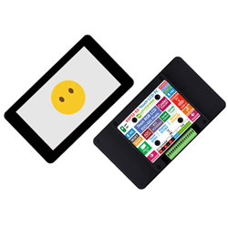
This is a microcontroller development board designed by Waveshare, supporting 2.4GHz Wi-Fi and BLE 5, integrating Flash and PSRAM, and featuring an onboard 7inch capacitive touch LCD screen capable of running GUI programs such as LVGL. It provides a variety of peripheral interfaces for HMI and related application development with the ESP32-S3. The audio section offers both 3.5mm and MX1.25 audio connectors, with an onboard ES8389 audio codec and ES7210 audio capture chip for speaker output and microphone capture.
| SKU | Product |
|---|---|
| 34894 | ESP32-S3-Touch-LCD-7C-BOX |
Features
- Equipped with Xtensa 32-bit LX7 dual-core processor, main frequency up to 240MHz
- Supports 2.4 GHz Wi-Fi (802.11 b/g/n) and Bluetooth 5 (LE) with an onboard antenna
- Built-in 512KB SRAM and 384KB ROM, stacked with 32MB Flash and 16MB PSRAM
- Onboard 7inch LCD capacitive touchscreen, 800 × 480 resolution, 65K colors
- Supports I2C interface control for capacitive touch, with 5-point touch, and supports interrupts
- Onboard ES8389 audio codec and ES7210 echo cancellation circuit
- Onboard voltage regulator, supporting 7 ~ 36V wide-voltage power supply
- Onboard RTC chip and battery holder, retaining time after power-off when a battery is installed
- Onboard BQ27220 fuel gauge for real-time battery capacity monitoring
- Onboard I2C interface, TF card slot, PH2.0 battery connector
- Onboard LED indicators for power status, battery charging status, and a user-definable STA status LED
- Supports flexible clock and independent power supply settings for precise control, enabling low-power modes in various scenarios
Onboard Resources
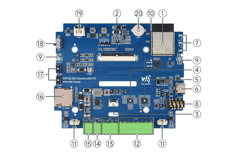
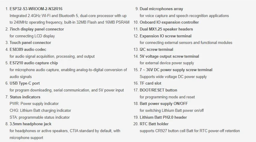
Dimensions
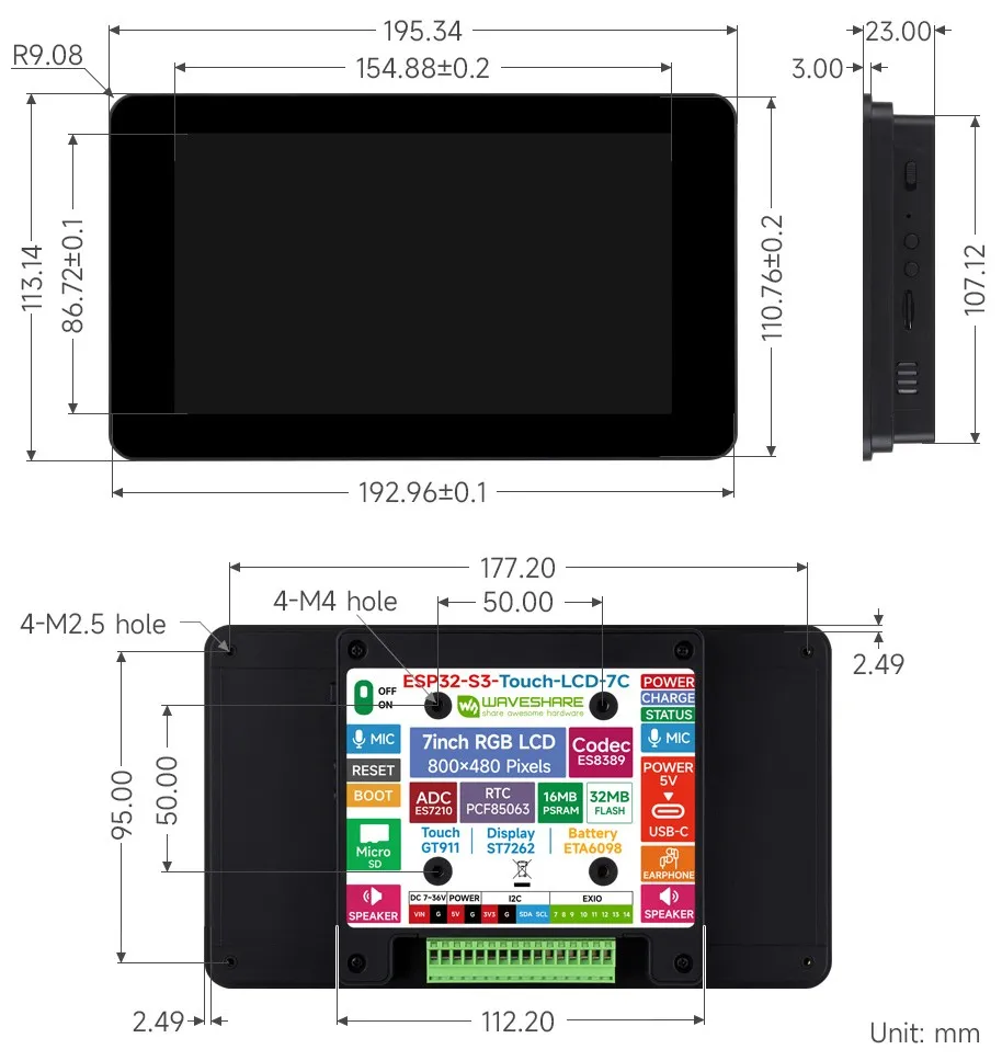
Working with Arduino
This chapter contains the following sections. Please read as needed:
Arduino Getting Started
New to Arduino ESP32 development and looking for a quick start? We have prepared a comprehensive Getting Started Tutorial for you.
- Section 0: Getting to Know ESP32
- Section 1: Installing and Configuring Arduino IDE
- Section 2: Arduino Basics
- Section 3: Digital Output/Input
- Section 4: Analog Input
- Section 5: Pulse Width Modulation (PWM)
- Section 6: Serial Communication (UART)
- Section 7: I2C Communication
- Section 8: SPI Communication
- Section 9: Wi-Fi Basics
- Section 10: Web Server
- Section 11: Bluetooth
- Section 12: LVGL GUI Development
- Section 13: Comprehensive Project
Note: This tutorial uses the ESP32-S3-Zero as a reference example, and all hardware code is based on its pinout. Before you start, we recommend checking the pinout of your development board to ensure the pin configuration is correct.
Setting Up the Development Environment
1. Installing and Configuring the Arduino IDE
- Please refer to the Arduino IDE Installation and Configuration Tutorial to download and install the Arduino IDE and add ESP32 board support.
2. Selecting Board and Port
- After connecting the ESP32-S3-Touch-LCD-7C to your computer, select the corresponding serial port in the "Tools" menu.
3. Example Code Package and Libraries
- The Arduino example programs and required library files for the ESP32-S3-Touch-LCD-7C are included in the example code package.
- After extraction, the Arduino examples are located in the
Arduino/examplesdirectory, and the library files are in theArduino/librariesdirectory. You can add the libraries to the Arduino IDE following the general Arduino tutorial.
ESP32-S3-Touch-LCD-7C Board Installation Requirements
| Board Name | Installation Requirement | Version Requirement |
|---|---|---|
| ESP32 by Espressif Systems | "Offline" / "Online" installation | 3.5.5 |
| ESP32-audioI2S-master | "Online" installation | 3.4.6 |
| LVGL | "Online" installation | 8.4.0 |
Parameter Configuration
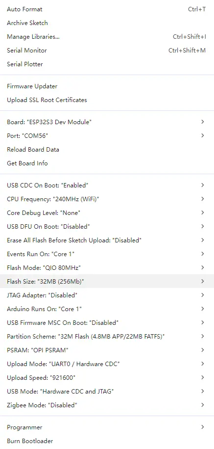
Example
| Example | Basic Description |
|---|---|
| 01_I2C | Test I2C interface communication |
| 02_RTC | Test RTC real-time clock functionality |
| 03_LCD | Test LCD display functionality |
| 04_ISOLATION_IO | Test isolated I/O functionality |
| 05_SD | Test TF card read/write functionality |
| 06_TOUCH | Test touchscreen functionality |
| 07_DISPLAY_BMP | Display BMP images |
| 08_BAT_INFO | Test battery information reading |
| 09_SPEAKER_MICROPHONE | Test speaker and microphone |
| 10_LVGL_CODEC | LVGL codec example |
01_I2C
Hardware Connection
- Connect the development board to a computer using a USB cable.
Code
I2C Backlight Control Code
Code Analysis
DEV_I2C_Init(): Initializes the I2C bus in preparation for communication with the I/O expansion chip.IO_EXTENSION_Init(): Initializes the external I/O expansion chip.IO_EXTENSION_Output(IO_EXTENSION_IO_2, 1/0): ControlsIO_2to output high/low level, used to turn the LCD backlight on/off.delay(500): Controls the blinking rhythm of the backlight to make it easy to observe whether the output is normal.
Operation Result
- You will see the LCD backlight blinking.
02_RTC
Hardware Connection
- Connect the development board to a computer using a USB cable.
Code
RTC Time Reading Code
Code Analysis
PCF85063A_Read_now(&Now_time): Reads the current time from the PCF85063A RTC intoNow_time.datetime_to_str(datetime_str, Now_time): Converts the time structure to a string for easy output and display.printf("Now_time is %s..."): Outputs the current time via serial port to verify whether the RTC is working properly.IO_EXTENSION_Rtc_Int_Read() == 0: Reads the RTC interrupt pin state; low level indicates the alarm has triggered.PCF85063A_Enable_Alarm(): Re-enables the alarm after it triggers, facilitating repeated trigger tests.delay(1000): Updates the time and checks the alarm every second.
Operation Result
The RTC time is printed over the serial port.
03_LCD
Hardware Connection
- Connect the development board to a computer using a USB cable.
Code
LCD Display Test Code
Code Analysis
Paint_DrawString_EN(...): Draws an English string at the specified coordinates, with configurable font, foreground color, and background color.Paint_DrawNum(...): Draws a floating-point number using the specified font and format parameters (used here to verify number rendering).Paint_DrawString_CN(...): Draws a Chinese string to verify Chinese font and display effects.
Operation Result
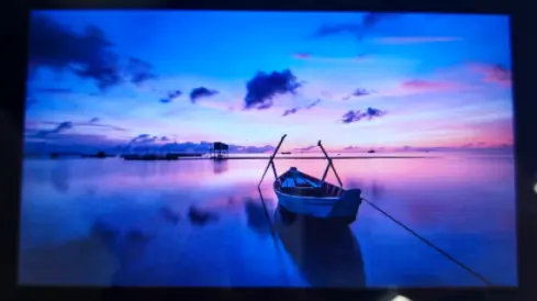
Test content is displayed on the screen.
You will see text, graphics, and image display effects.

04_ISOLATION_IO
Hardware Connection
- Connect the development board to a computer using a USB cable.
Operation Result
- After successful flashing, if all I/O connections are successful, the screen turns green; otherwise, it turns red.
05_SD
Hardware Connection
- Connect the development board to a computer using a USB cable.
- Insert a TF card into the development board.
Code Analysis
setup():- Initialize the TF card.
loop():- Tests TF card read/write functionality.
Operation Result
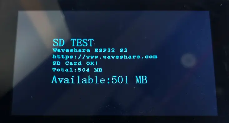
The screen displays TF card information and test results.
06_TOUCH
Hardware Connection
- Connect the development board to a computer using a USB cable.
Code Analysis
setup():- Initializes the touchscreen.
loop():- Tests multi-touch functionality.
Operation Result
- Touching the screen works normally.
- You will see touch points displayed on the screen.
07_DISPLAY_BMP
Hardware Connection
- Connect the development board to a computer using a USB cable.
- Insert a TF card containing BMP images.
Code Analysis
setup():- Initializes the TF card and LCD.
loop():- Reads and displays BMP images.
Operation Result
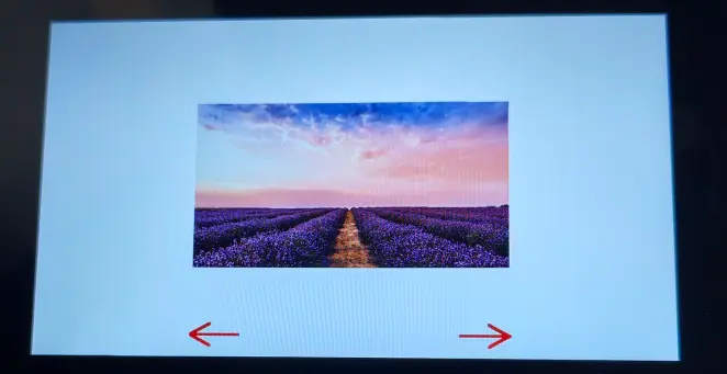
BMP images are displayed on the screen.
08_BAT_INFO
Hardware Connection
- Connect the development board to a computer using a USB cable.
- Connect a Lithium battery to the development board.
Code
Battery Information Reading Code
Code Analysis
BATTERY_CAPACITY_MAH: Configures the nominal battery capacity for charge estimation and display.Serial.begin(115200): Initializes serial output for debugging.DEV_I2C_Init(): Initializes the I2C bus for communication with the fuel gauge and I/O expansion chip.battery_init(BATTERY_CAPACITY_MAH): Initializes the battery/fuel-gauge module and returns the current battery status.IO_EXTENSION_Init()/display_init(): Initializes the I/O expansion and display modules in preparation for UI display.battery_get_info(&bat_info): Periodically reads battery information and stores it inbat_info.display_show_info(...)/display_show_not_connect()/display_show_error(...): Displays battery info, not-connected prompt, or error message on the screen according to the read status.delay(1000): Refreshes the battery information display every second.
Operation Result
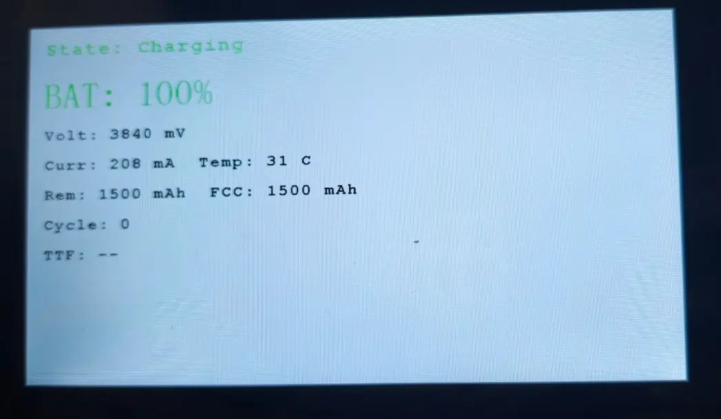
Battery information is displayed on the screen.
09_SPEAKER_MICROPHONE
Hardware Connection
- Connect the development board to a computer using a USB cable.
- Connect the speaker and microphone.
Code Analysis
setup():- Initializes the audio codec.
loop():- Tests audio input and output functionality.
Operation Result
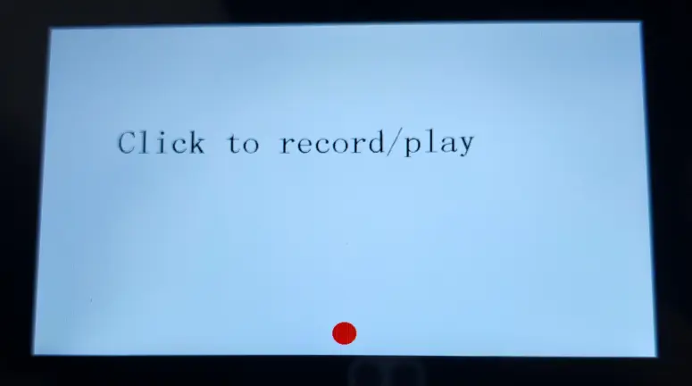
You can record audio via the microphone and play it back through the speaker.
10_LVGL_CODEC
Hardware Connection
- Connect the development board to a computer using a USB cable.
Code Analysis
setup():- Initializes the LVGL graphics library.
loop():- Tests LVGL codec functionality.
Operation Result
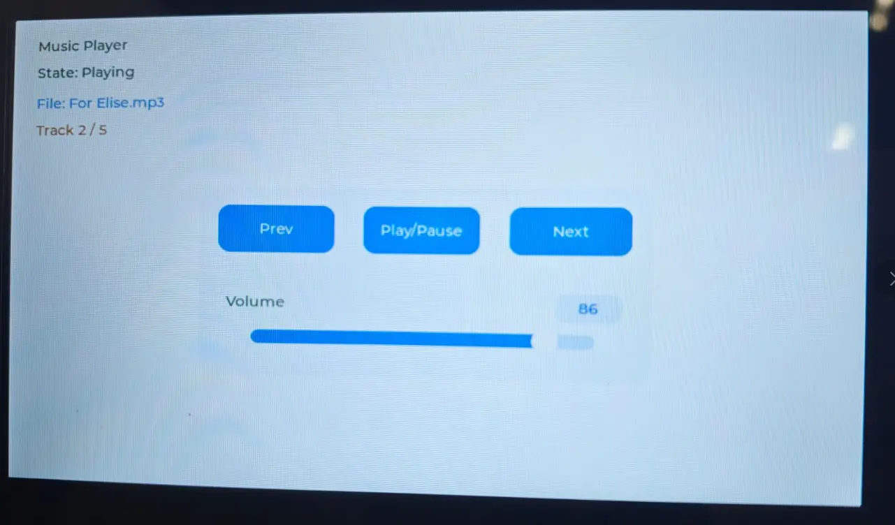
The LVGL interface is displayed on the screen, and music can be played normally (a TF card must be inserted in advance).
Working with ESP-IDF
Overview
The ESP32-S3-Touch-LCD-7C board features a 7inch capacitive touchscreen, audio module, and commonly used peripherals, making it suitable for applications such as graphical user interface display, voice interaction, and human-machine interface development.
For the ESP32-S3-Touch-LCD-7C development board, the examples default to ESP-IDF V5.5.3. If compilation fails with other versions, you can fall back to this version for testing.
Getting Started
This chapter includes the following sections:
- ESP-IDF Getting Started
- Setting Up the Development Environment (Windows)
- Common Example Descriptions (Brief Overview and Code Explanation)
ESP-IDF Getting Started
New to ESP32 ESP-IDF development and looking to get started quickly? We have prepared a general Getting Started Tutorial for you.
- Section 1: Environment Setup
- Section 2: Running Examples
- Section 3: Creating a Project
- Section 4: Using Components
- Section 5: Debugging
- Section 6: FreeRTOS
- Section 7: Peripherals
- Section 8: Wi-Fi Programming
- Section 9: BLE Programming
Please Note: This tutorial uses the ESP32-S3-Zero as a teaching example, and all hardware code is based on its pinout. Before you start, it is recommended that you check the pinout of your development board to ensure the pin configuration is correct.
Setting Up the Development Environment
The following guide uses Windows as an example, demonstrating development using VS Code + the ESP-IDF extension. macOS and Linux users should refer to the official documentation.
The screenshots in this section use ESP-IDF V5.5.2 as an example. When installing, please select the ESP-IDF version that matches your board's example.
Install the ESP-IDF Development Environment
Download the installation manager from the ESP-IDF Installation Manager page. This is Espressif's latest cross-platform installer. The following steps demonstrate how to use its offline installation feature.
Click the Offline Installer tab on the page, then select Windows as the operating system and the ESP-IDF version you need (the version shown in the screenshot is for reference only — choose the version that fits your actual needs).
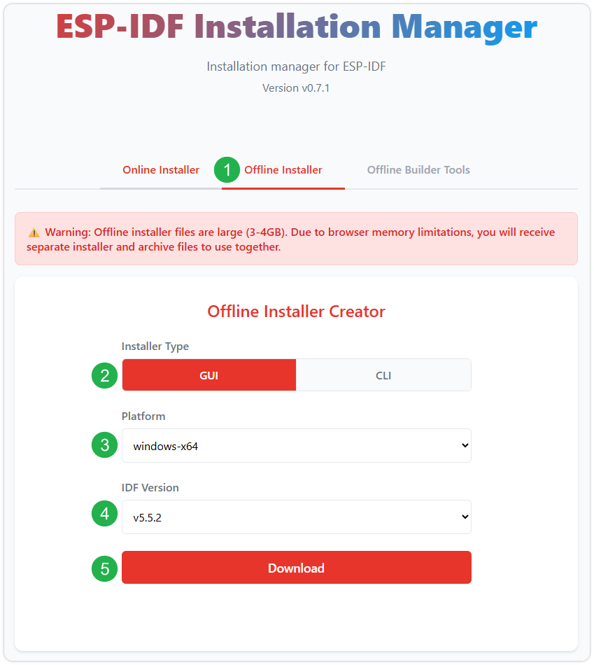
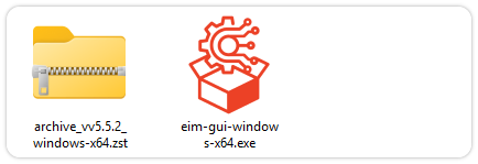
After confirming your selection, click the download button. The browser will automatically download two files: the ESP-IDF Offline Package (.zst) and the ESP-IDF Installer (.exe).
Please wait for both files to finish downloading.
Once the download is complete, double-click to run the ESP-IDF Installer (eim-gui-windows-x64.exe).
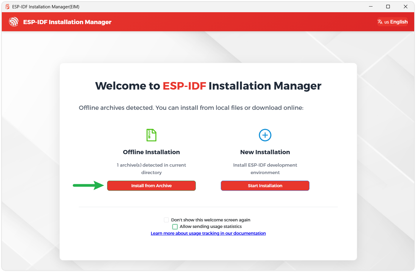
The installer will automatically detect if the offline package exists in the same directory. Click Install from archive.
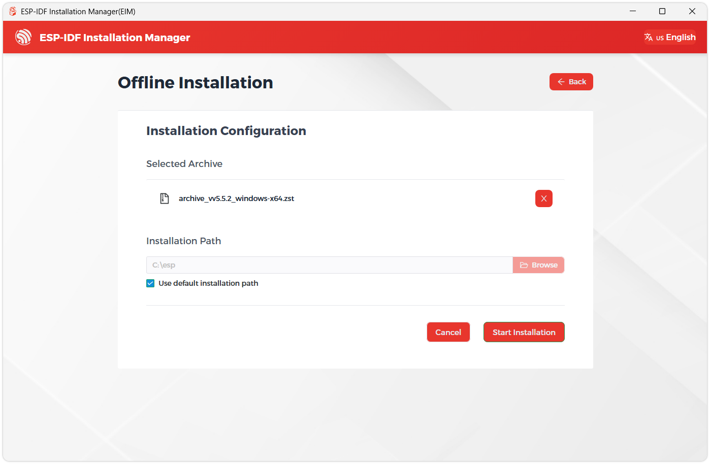
Next, select the installation path. We recommend using the default path. If you need to customize it, ensure the path does not contain Chinese characters or spaces. Click Start installation to proceed.
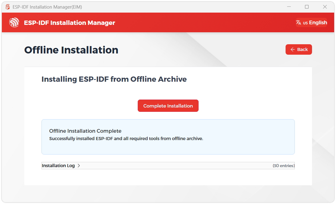
When you see the following screen, the ESP-IDF installation is successful.
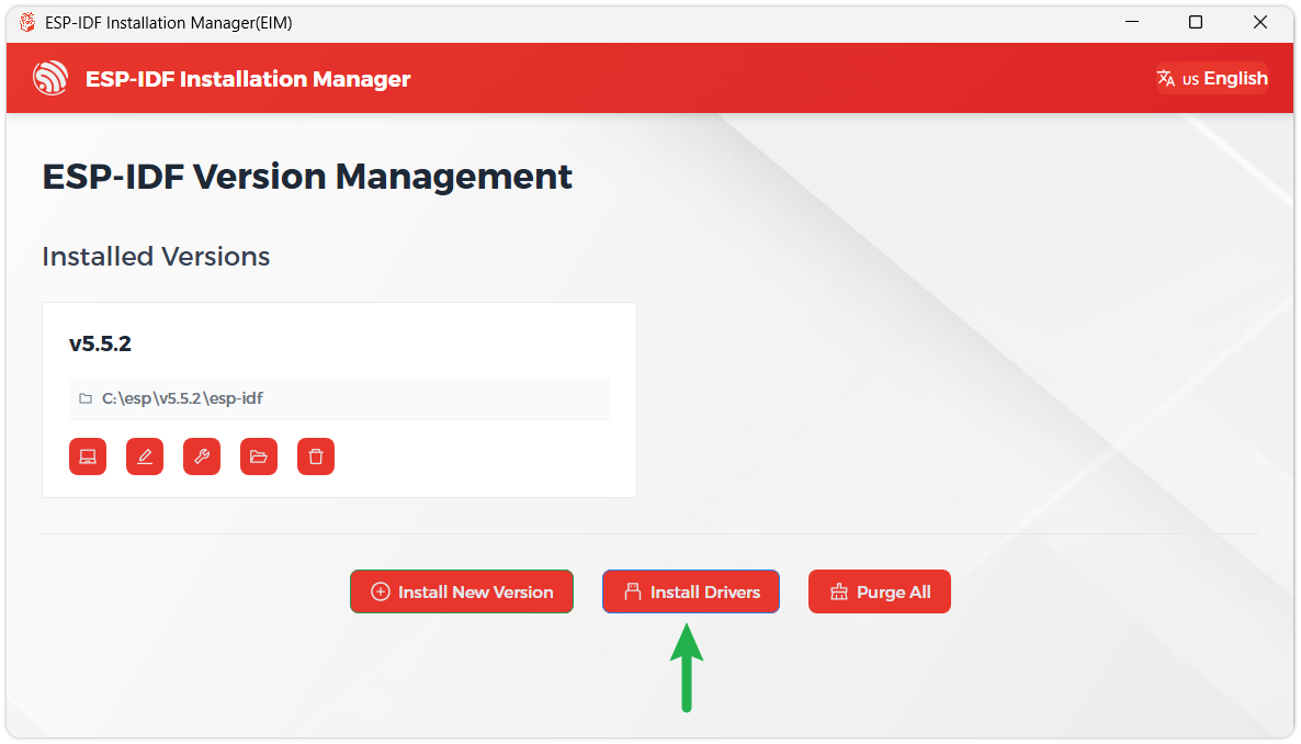
We recommend installing the drivers as well. Click Finish installation, then select Install driver.
Install Visual Studio Code and the ESP-IDF Extension
Download and install Visual Studio Code.
During installation, it is recommended to check Add "Open with Code" action to Windows Explorer file context menu to facilitate opening project folders quickly.
In VS Code, click the Extensions icon
 in the Activity Bar on the side (or use the shortcut Ctrl + Shift + X) to open the Extensions view.
Enter ESP-IDF in the search box, locate the ESP-IDF extension, and click Install.
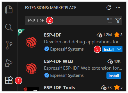
For ESP-IDF extension versions ≥ 2.0, the extension will automatically detect and recognize the ESP-IDF environment installed in the previous steps, requiring no manual configuration.
If installation fails or a reinstall is needed, you can try deleting the C:\Users\%Username%\esp and C:\Users\%Username%\.espressif folders and then retry.
Flashing Example
After installing the ESP-IDF development environment, select the folder to open the example.
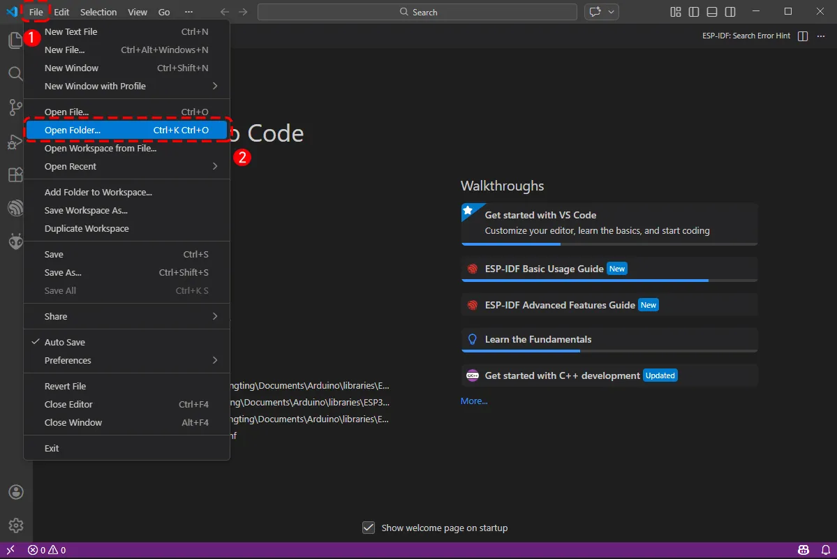
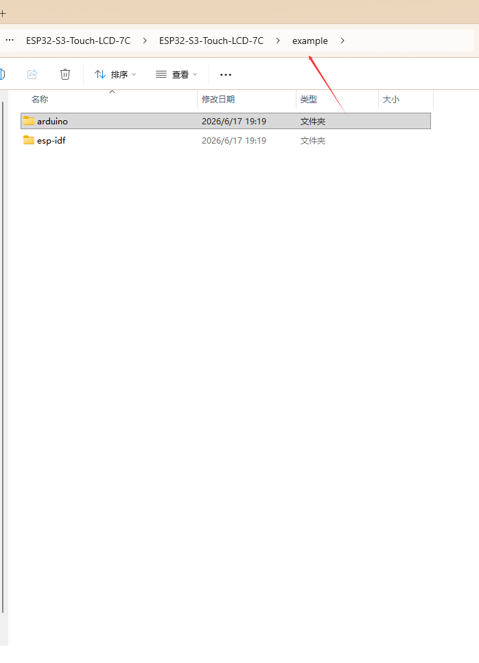
In the pop-up window, select the example under the ESP-IDF directory within the extracted example package, and click to select a file.
To upload the corresponding code to the ESP32-S3, use a Type-C to Type-A cable to connect the USB TO UART Type-C interface of the ESP32-S3-Touch-LCD-7C to a USB port on your computer.
If this is the first time flashing a new project, you need to select the detected COM port. For example, here it is detected as COM36.
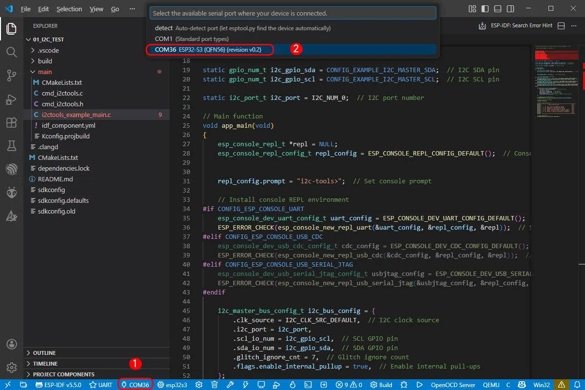
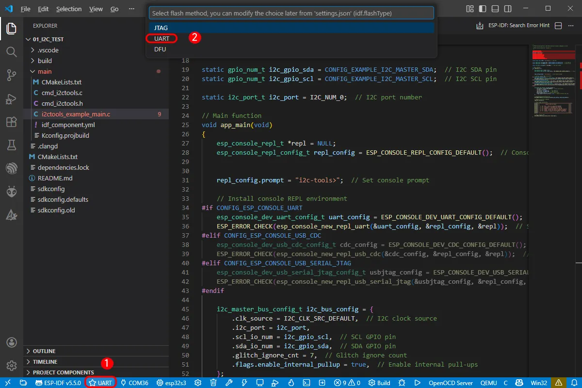
Select the download method: UART.
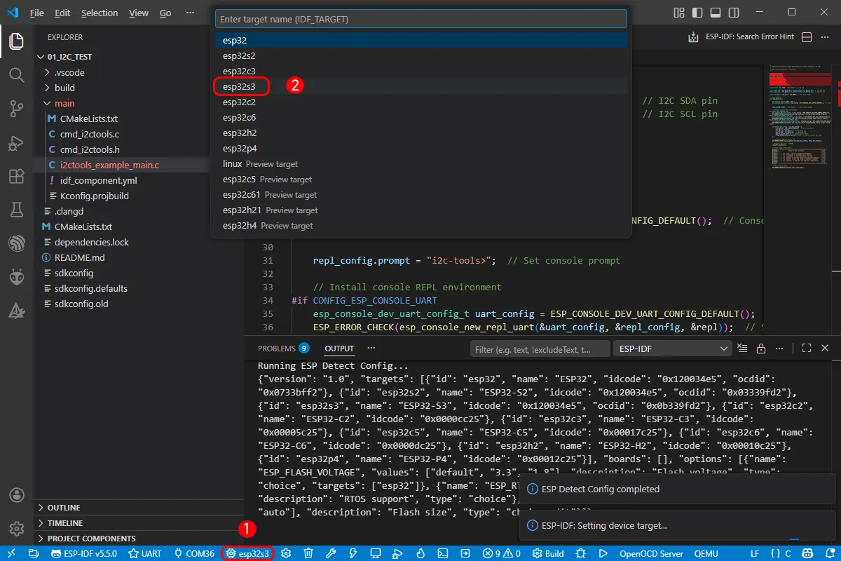
Next, select the main chip as ESP32S3.
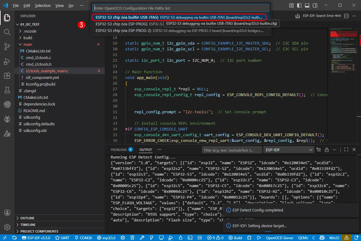
- Select the openocd path. This does not affect the process, so choose the first one.
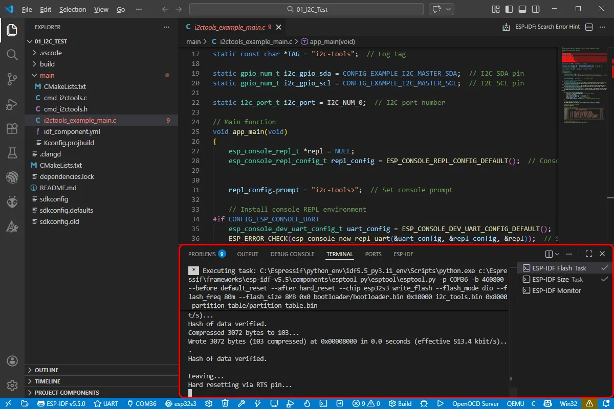
Click the one-click Build Flash Monitor button below to sequentially execute Build --> Flash --> Monitor.
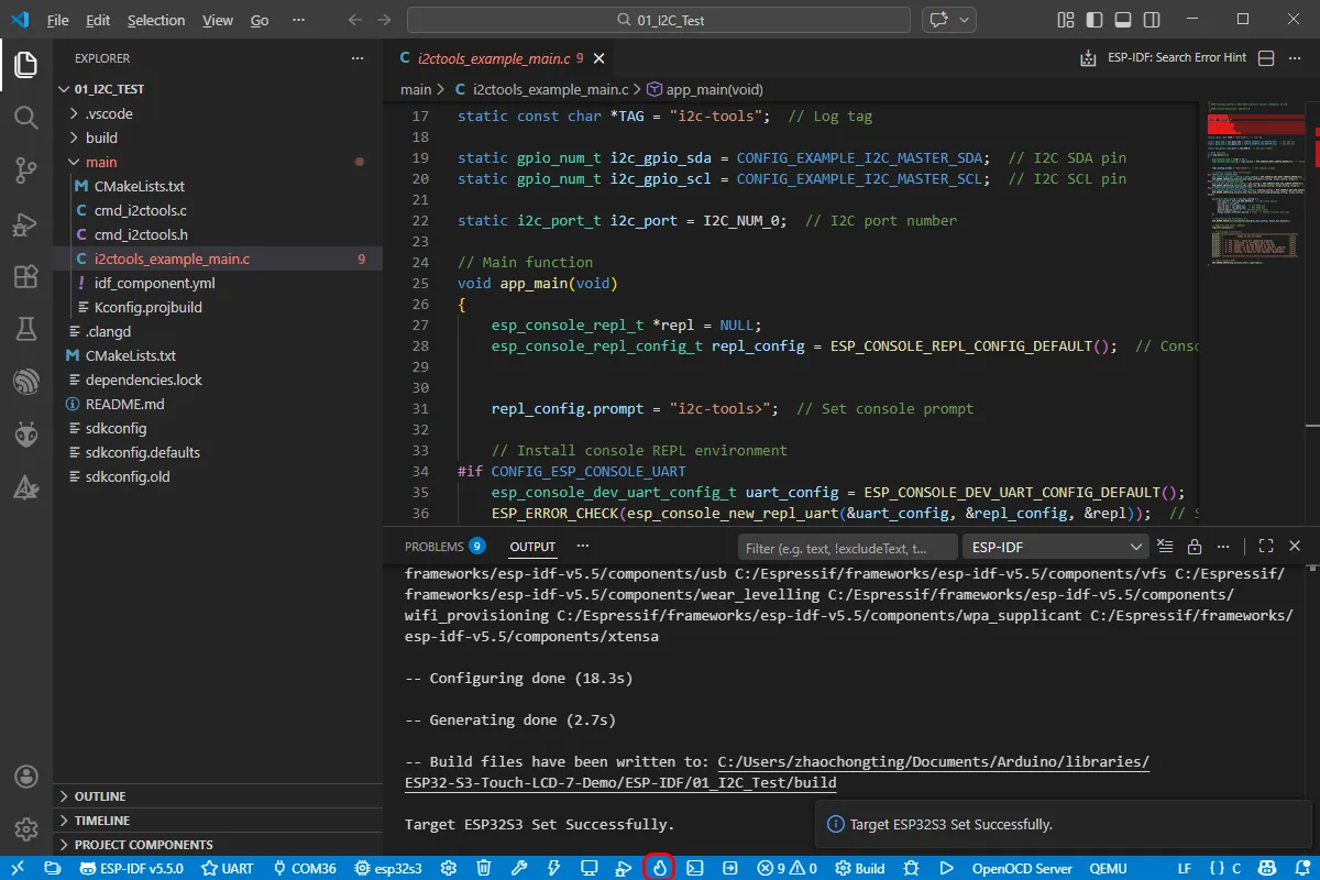
The development board has an onboard automatic download circuit, so no manual operation is required for automatic download. Wait for compilation and flashing to complete. The first compilation may take a while.
Example
Below are the purpose, key points, and operational effects for each example (for quick start).
| Example | Basic Description |
|---|---|
| 01_I2C | Test I2C interface communication |
| 02_RTC | Test RTC real-time clock functionality |
| 03_LCD | Test LCD display functionality |
| 04_ISOLATION_IO | Test isolated I/O functionality |
| 05_BAT_INFO | Test battery information reading |
| 06_SD | Test TF card read/write functionality |
| 07_TOUCH | Test touchscreen functionality |
| 08_DISPLAY_BMP | Display BMP images |
| 09_SPEAKER_MICROPHONE | Test speaker and microphone |
| 10_LVGL_CODEC | LVGL codec example |
01_I2C
Hardware Connection
- Connect the development board to a computer using a USB cable.
Code
Backlight Control Code
Code Analysis
while (1): Continuously loops the backlight on/off test logic.IO_EXTENSION_Output(IO_EXTENSION_IO_2, 1): SetsIO_2of the I/O expansion chip to high level to turn on the LCD backlight.IO_EXTENSION_Output(IO_EXTENSION_IO_2, 0): SetsIO_2to low level to turn off the LCD backlight.vTaskDelay(500 / portTICK_PERIOD_MS): Delays for approximately 500 ms to control the blinking rhythm of the backlight.
Operation Result
- You will see the LCD backlight blinking.
02_RTC
Hardware Connection
- Connect the development board to a computer using a USB cable.
Code
RTC Initialization Code
Code Analysis
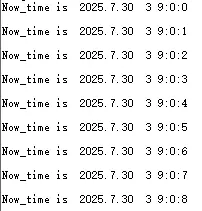
DEV_I2C_Init(): Initializes the I2C bus in preparation for communication with the RTC and I/O expansion chip.IO_EXTENSION_Init(): Initializes the external I/O expansion chip (used for reading/writing peripheral signals such as RTC interrupts).PCF85063A_Init(): Initializes the PCF85063A RTC chip.PCF85063A_Set_All(Set_Time): Sets the current time on the RTC.PCF85063A_Set_Alarm(Set_Alarm_Time): Sets the RTC alarm time.PCF85063A_Enable_Alarm(): Enables the alarm interrupt to trigger alarm notifications.
Operation Result
The RTC time is printed over the serial port.
03_LCD
Hardware Connection
- Connect the development board to a computer using a USB cable.
Code Analysis
app_main():- Initializes the LCD display.
- Tests LCD display functionality.
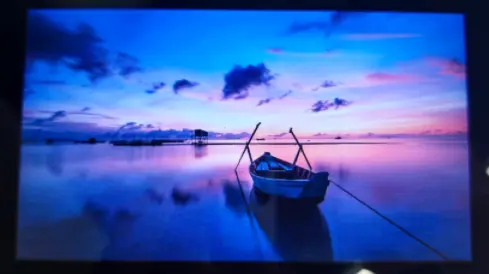
- Displays text, graphics, and images.
Operation Result
After successful flashing, the screen displays test content.
You will see text, graphics, and image display effects.
04_ISOLATION_IO
Hardware Connection
- Connect the development board to a computer using a USB cable.
Code Analysis
app_main():- Initializes the isolated I/O.
- Tests isolated I/O input and output functionality.
Operation Result
- After successful flashing, if all I/O connections are successful, the screen turns green; otherwise, it turns red.
05_BAT_INFO
Hardware Connection
- Connect the development board to a computer using a USB cable.
- Connect a Lithium battery to the development board.
Code
Battery Information Display Code
Code Analysis
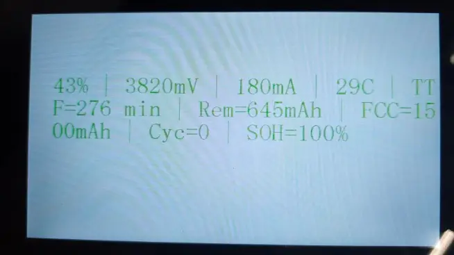
bat_info.ma > 0: In the current logic, positive current is treated as charging state; otherwise, it is treated as discharging.sprintf(bat, "...", ...): Formats the battery percentage, voltage, current, temperature, remaining time, and other fields into a string for screen display.Paint_DrawString_EN(...): Draws the battery information on the LCD; usesGREENfor charging andREDfor discharging to indicate status.waveshare_rgb_lcd_display(BlackImage): Refreshes the screen to display the drawn content.ESP_LOGI("BQ27220", "...", ...): Outputs the same battery information to the serial log for debugging and cross-checking.
Operation Result
After successful flashing, the screen displays battery information.
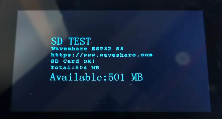
06_SD
Hardware Connection
- Connect the development board to a computer using a USB cable.
- Insert a TF card into the development board.
Code Analysis
app_main():- Initializes the TF card.
- Tests TF card read/write functionality.
Operation Result
After successful flashing, the screen displays TF card information and test results.
07_TOUCH
Hardware Connection
- Connect the development board to a computer using a USB cable.
app_main():- Initializes the display and touchscreen drivers.
- Reads touchscreen data and displays it.
Operation Result
- After successful flashing, the touchscreen works normally, and the corresponding touch UI elements are displayed on the screen.
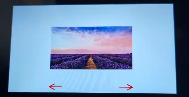
08_DISPLAY_BMP
Hardware Connection
- Connect the development board to a computer using a USB cable.
- Insert a TF card containing BMP images.
Code Analysis
app_main():- Initializes the TF card and LCD.
- Reads and displays BMP images.
Operation Result
After successful flashing, BMP images are displayed on the screen.
09_SPEAKER_MICROPHONE
Hardware Connection
- Connect the development board to a computer using a USB cable.
- Connect the speaker and microphone.
Code
Audio Touch Control Code
Code Analysis
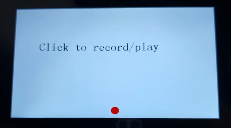
touch_gt911_read_point(1): Reads touch point data from the GT911 touch controller (here, one set of data is taken).point_data.cnt == 1: Only enters the processing logic for a single-touch event to avoid multi-touch interference.prev_x / prev_y: Stores the previous touch coordinates to filter out repeated triggers.- Coordinate range check: When the touch point falls within
(x: 390~420, y: 420~480), it is considered a tap on the control area on the interface. play_or_pause(...): Executes play/pause control according to the current state (in the example, it is called twice in succession to demonstrate the control flow).Paint_DrawCircle(...)/Paint_DrawString_EN(...): Draws the button and prompt text, and refreshes the display viawaveshare_rgb_lcd_display(...).
Operation Result
After successful flashing, you can record audio via the microphone and play it back through the speaker.
10_LVGL_CODEC
Hardware Connection
- Connect the development board to a computer using a USB cable.
Code
LVGL Codec Initialization Code
Code Analysis
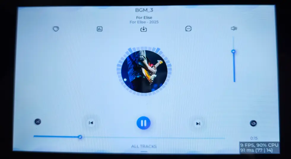
speaker_codec_init(): Initializes the audio codec hardware.speaker_codec_volume_set(50, NULL): Sets the volume to 50 (the exact range depends on the implementation).speaker_player_register_callback(...): Registers a playback callback function to receive playback status events.speaker_player_init(): Initializes the player module.lvgl_port_lock(-1)/lvgl_port_unlock(): LVGL APIs are not thread-safe, so lock before calling UI functions and unlock afterward.user_lv_demo_music(): Launches the example LVGL music interface.IO_EXTENSION_Pwm_Output(100): Outputs PWM via the I/O expander to set the backlight brightness to maximum.waveshare_rgb_lcd_bl_on(): Turns on the LCD backlight output.
Operation Result
After successful flashing, the LVGL interface is displayed on the screen, and music can be played normally (a TF card must be inserted in advance).
Using Factory Firmware
This firmware is used to demonstrate relevant features and will continue to be iterated upon. If you encounter any issues during use, please feel free to provide feedback. Once the issue is confirmed, the version will be updated.
This chapter includes the following sections:
Test Preparation
- Type-C data cable
- Card reader
- TF card
Program Overview
The applications include: SquareLine example, handwriting test, image display, music player, AI conversation, settings (WLAN, sound adjustment, backlight adjustment, battery voltage and CPU temperature reading, isolated I/O test), and microphone test.
Program Usage
Below is a brief description of the purpose and functionality of each program.
For the image display and music playback tests, you need to copy the two folders from ./firmware/sdcard to the TF card. The TF card's file system must be formatted as FAT32; otherwise, clicking the icon will restart the system.
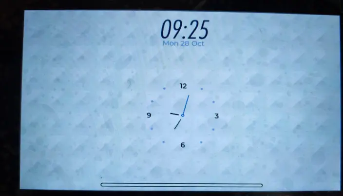
Squareline
This example runs the SquareLine example interface.
Operation Result
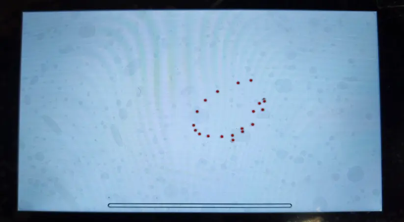
DrawPanel
This example tests if the touchscreen is functioning properly.
Operation Result
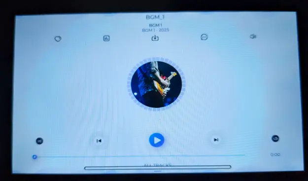
MusicPlayer
This example plays music from the TF card. The volume can be adjusted using the speaker button on the right.
Operation Result
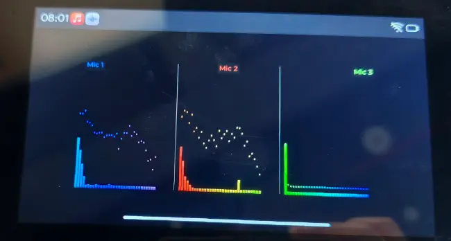
SpecAnalyzer
This example tests if the microphone is working properly by capturing sound and displaying it via animation.
Operation Result
Settings
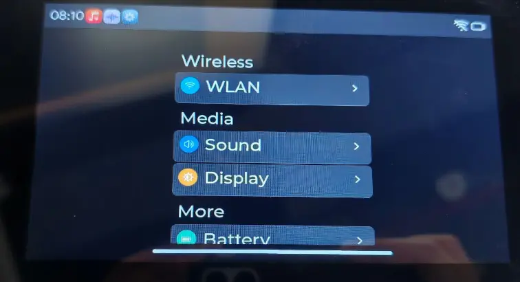
This example is used to view and adjust system settings. Currently it includes entry points for WLAN, sound, backlight, battery information, and isolated I/O test.
Operation Result
WLAN
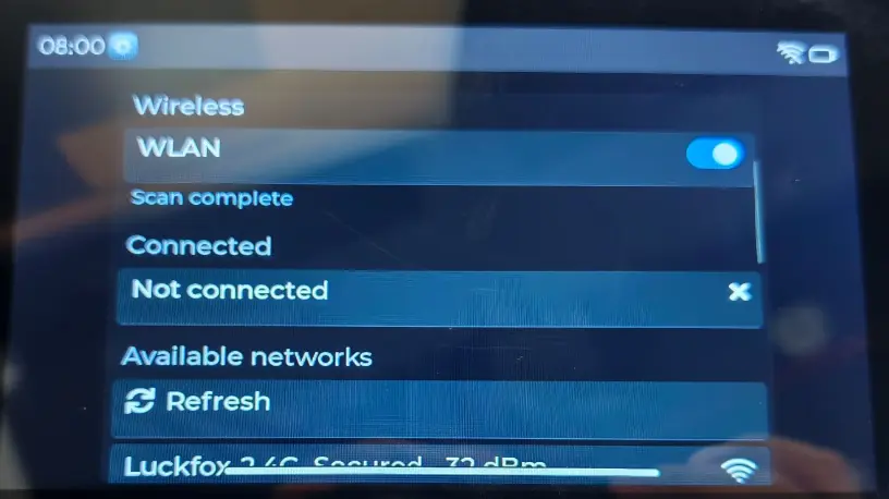
This example is used to connect to a Wi-Fi network. After entering the page, you can turn on the WLAN switch, scan for nearby hotspots, select the target network, and enter the password to complete the connection. Once connected, it can be used for subsequent network-related functional tests.
Operation Result
Isolationio
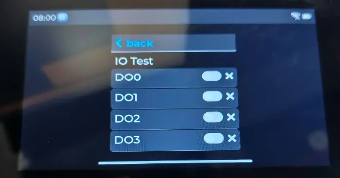
This example is used to test the isolated I/O function. Before use, connect the corresponding DI and DO pins, then toggle the DO state via the interface and observe whether the DI input changes as expected to confirm that the isolated input/output is working properly.
Operation Result
Factory Reset
If you have flashed other programs and cannot test the factory firmware, you can restore the factory settings using the method below:
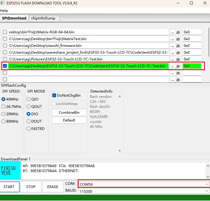
First, you need to understand how to use the Flash Tool. Refer to Firmware Flashing and Erasing Tutorial.
Add
./firmware/ESP32-S3-Touch-LCD-7C-BOX-Test.binto the Flash Tool with the flash address 0x00.Connect the development board to your computer, check the COM port in Device Manager, then select the corresponding COM port in the Flash Tool and click Start. Wait for the flashing to complete, then press the RESET button.
Resources
1. Hardware Resources
Development Board Design File
2. Technical Manuals
ESP32-S3 Chip Official Manuals
Datasheets
3. Example
4. Software Tools
- Arduino IDE Official Download Link
- VS Code Official Download Link
- SSCOM Serial Port and Network Debug Assistant
5. Other Resource Links
- ESP32-Arduino Official Documentation
- ESP32-Arduino Official Repository
- ESP-IDF Official Repository
- LVGL Official Documentation
Support
Monday-Friday (9:30-6:30) Saturday (9:30-5:30)
Email: services01@spotpear.com
[Tutorial Navigation]
- Product Introduction
- Dimensions
- Working with Arduino
- Arduino Getting Started
- Setting Up the Development Environment
- 1. Installing and Configuring the Arduino IDE
- 2. Selecting Board and Port
- 3. Example Code Package and Libraries
- Parameter Configuration
- Example
- Working with ESP-IDF
- Overview
- Getting Started
- ESP-IDF Getting Started
- Setting Up the Development Environment
- Flashing Example
- Example
- Using Factory Firmware
- Test Preparation
- Program Overview
- Program Usage
- Factory Reset
- Resources
- Support