




- sales/support
Google Chat:---
- sales
+86-0755-88291180
- sales01
sales@spotpear.com
- sales02
dragon_manager@163.com
- support
tech-support@spotpear.com
- CEO-Complaints
zhoujie@spotpear.com
- Only Tech-Support
WhatsApp:13246739196
- Purchase/Shipping/Refund
WhatsApp:13424403025
- HOME
- >
- ARTICLES
- >
- Common Moudle
- >
- ESP
ESP32-S3-LR1121-XF User Guide
Features
The ESP32-S3-LR1121-XF is a LoRa development board based on the ESP32-S3 main controller and integrated with the LR1121 RF chip, enabling longer-distance and more stable wireless communication under low power consumption. Compared to traditional LoRa solutions, it offers significant advantages in link reliability, energy efficiency, and multi-band adaptability.
Leveraging LoRa modulation technology, the system ensures long-distance communication while maintaining good anti-interference performance and ultra-low power consumption. When paired with a LoRa gateway, it can connect to servers like TTN and ChirpStack, facilitating cloud integration and application validation. The main board supports multi-band configuration and a rich set of peripheral interfaces, making it suitable for various IoT scenarios such as outdoor communication, sensor networks, emergency interconnection, and community networking.
Onboard Resources
- Powered by a high-performance Xtensa® 32-bit LX7 dual-core processor, with a main frequency of up to 240 MHz.
- Supports 2.4 GHz Wi-Fi (802.11 b/g/n) and Bluetooth® 5 (LE), meeting diverse wireless requirements.
- Features 512KB SRAM and 384KB ROM internally, with stacked 4MB Flash and 2MB PSRAM.
- Utilizes the castellated design for enhanced integration, facilitating user-customized baseboard design.
- Rich peripherals including 4 × SPI, 2 × I2C, 3 × UART, 2 × I2S, and 2 × ADC.
- Equipped with the Semtech LR1121 low-power LoRa transceiver.
- Supports Sub-GHz (150MHz ~ 960MHz), S-Band (1.9GHz ~ 2.1GHz), and 2.4GHz ISM bands.
- Enables connection to the cloud via LoRa or LoRaWAN protocols combined with a gateway, building low-power wide-area networks.
- Supports LoRa, (G)FSK, and LR-FHSS modulation schemes, compatible with SX126x / SX127x frequency bands for easy product upgrades.
- Integrated AES-128 encryption engine enhances data security.
- Onboard TCXO ensures frequency stability under high and low temperature conditions.
- Suitable for IoT applications such as industrial telemetry, smart homes, environmental monitoring, and remote data acquisition.
- Comes with C example programs and a user manual for easy development and rapid application.
Specifications
| Item | ESP32-S3-LR1121-HF | ESP32-S3-LR1121-LF |
|---|---|---|
| Operating Frequency Bands | 850 ~ 930MHz 1900 ~ 2100MHz 2400 ~ 2500MHz | 410 ~ 510MHz 1900 ~ 2100MHz 2400 ~ 2500MHz |
| Modulation | LoRa, (G)FSK, LR-FHSS | LoRa, (G)FSK, LR-FHSS |
| Communication Rate | LoRa: 0.091 ~ 62.5Kbps (G)FSK: 0.6 ~ 300Kbps | LoRa: 0.091 ~ 62.5Kbps (G)FSK: 0.6 ~ 300Kbps |
| Transmission Power | -9 ~ 22dBm@Sub-GHz Bands -18 ~ 13dBm@ISM Bands | -9 ~ 22dBm@Sub-GHz Bands -18 ~ 13dBm@ISM Bands |
| Receive Sensitivity | -127dBm@Sub-GHz Bands, SF=7, CR4_5, BW=125KHz -111dBm@ISM Bands, SF=7, CR4_5, BW=800KHz | -127dBm@Sub-GHz Bands, SF=7, CR4_5, BW=125KHz -111dBm@ISM Bands, SF=7, CR4_5, BW=800KHz |
| Reference Communication Distance | Sub-GHz Bands: 5km ISM Bands: 2km | Sub-GHz Bands: 5km ISM Bands: 2km |
| Spreading Factor | SF5 ~ SF12 | SF5 ~ SF12 |
| Logic Level | 3.3V (Level shifters required for other logic levels) | 3.3V (Level shifters required for other logic levels) |
| Module Current Consumption | Tx Current: 111.2mA@22dBm, 49.6mA@13dBm Rx Current: 9.2mA@125KHz Sub-GHz, 8.1mA@125KHz ISM | Tx Current: 87.7mA@22dBm, 52.7mA@13dBm Rx Current: 9.2mA@125KHz Sub-GHz, 8.1mA@125KHz ISM |
| Antenna Connector | IPEX-1 | IPEX-1 |
| Antenna Protection | TVS Protection | TVS Protection |
| Operating Temperature | -40 ~ 85℃ | -40 ~ 85℃ |
| Interface Type | Castellated / Pin Headers, 2.54mm pitch | Castellated / Pin Headers, 2.54mm pitch |
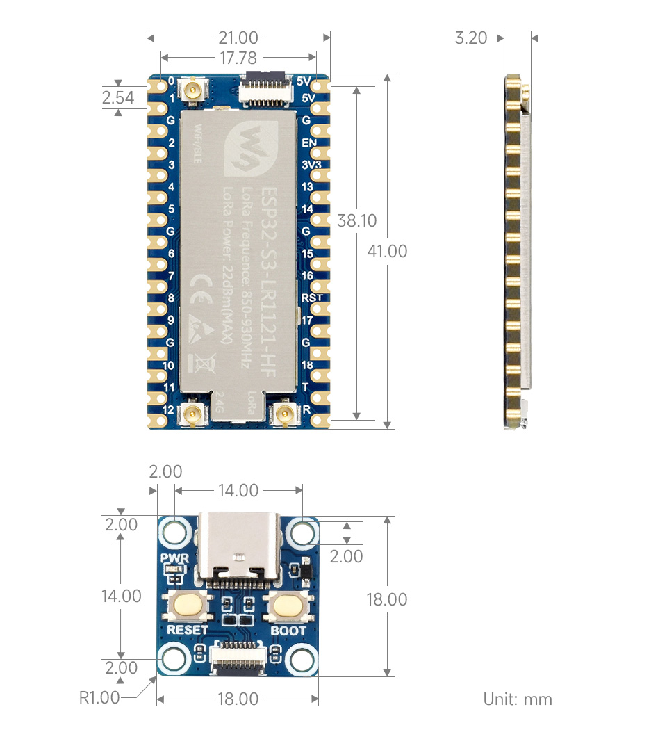
| Dimensions | 19.00 × 22.00mm | 19.00 × 22.00mm |
Interface Description
ESP32-S3-LR1121-XF Pinout Table (click to expand)
Dimensions
Working with Arduino
This chapter contains the following sections. Please read as needed:
Arduino Getting Started
New to Arduino ESP32 development and looking for a quick start? We have prepared a comprehensive Getting Started Tutorial for you.
- Section 0: Getting to Know ESP32
- Section 1: Installing and Configuring Arduino IDE
- Section 2: Arduino Basics
- Section 3: Digital Output/Input
- Section 4: Analog Input
- Section 5: Pulse Width Modulation (PWM)
- Section 6: Serial Communication (UART)
- Section 7: I2C Communication
- Section 8: SPI Communication
- Section 9: Wi-Fi Basics
- Section 10: Web Server
- Section 11: Bluetooth
- Section 12: LVGL GUI Development
- Section 13: Comprehensive Project
Note: This tutorial uses the ESP32-S3-Zero as a reference example, and all hardware code is based on its pinout. Before you start, we recommend checking the pinout of your development board to ensure the pin configuration is correct.
Setting Up Development Environment
1. Installing and Configuring Arduino IDE
Please refer to the tutorial Installing and Configuring Arduino IDE to download and install the Arduino IDE and add ESP32 support.
Example Usage Instructions
Download the examples, navigate to ESP32-S3-LR1121-XF/esp32s3/Arduino, and copy waveshare_lora_1121 to the libraries folder of your project folder. The project folder path can be found under File -> Preferences -> Sketchbook location
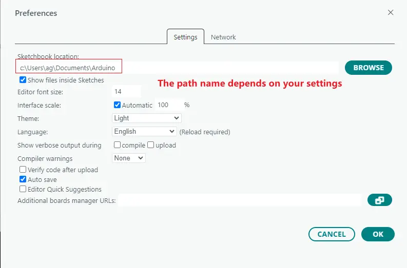
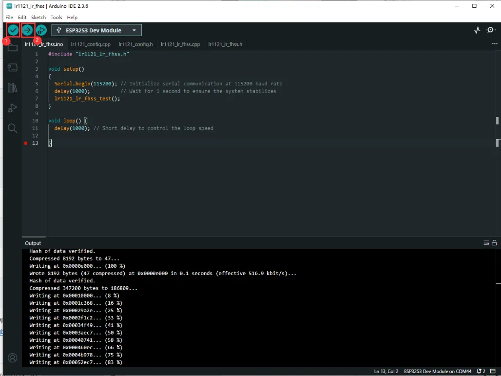
After copying, open the Arduino IDE. You can find all examples under File -> Examples -> waveshare lora spi. Open one to flash and test. Once the environment is set up, select the correct board and port. If you are unsure how to flash, refer to the image below:
①: Compile the demo
②: Complie and upload
3. Arduino Parameter Settings
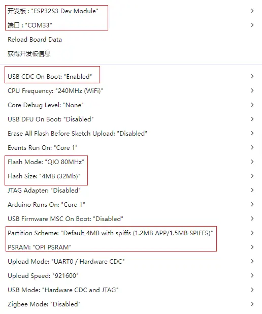
Note: Please ensure the configuration follows the parameters above; otherwise, the program may not function correctly.
Example
The demos are located in the Arduino directory of the ESP32-S3-LR1121-XF-Demo.zip. The following example names align with the directory structure of the ESP32-S3-LR1121-XF example package, allowing for quick location of corresponding functionalities:
| Demo | Basic Description |
|---|---|
| lr1121_cad | Perform Channel Activity Detection (CAD) - LoRa only |
| lr1121_firmware_update | LR1121 firmware update tool |
| lr1121_lr_fhss | Transmit LR-FHSS data packets |
| lr1121_per | Perform Packet Error Rate (PER) test — Tx and Rx roles |
| lr1121_ping_pong | Initiate data exchange between two devices |
| lr1121_read | Enter receive mode |
| lr1121_sigfox | Send Sigfox-compliant uplink |
| lr1121_spectral_scan | Obtain inst-RSSI values in Rx mode to form a heatmap |
| lr1121_spetrum_display | Obtain inst-RSSI values in Rx mode to form a dynamic spectrum curve |
| lr1121_tx_cw | Tx Continuous Wave mode |
| lr1121_tx_infinite_preamble | Transmit infinite preamble |
| lr1121_write | Send data periodically |
| lr1121_LoRaWAN | Simple LoRaWAN Class A application |
lr1121_cad
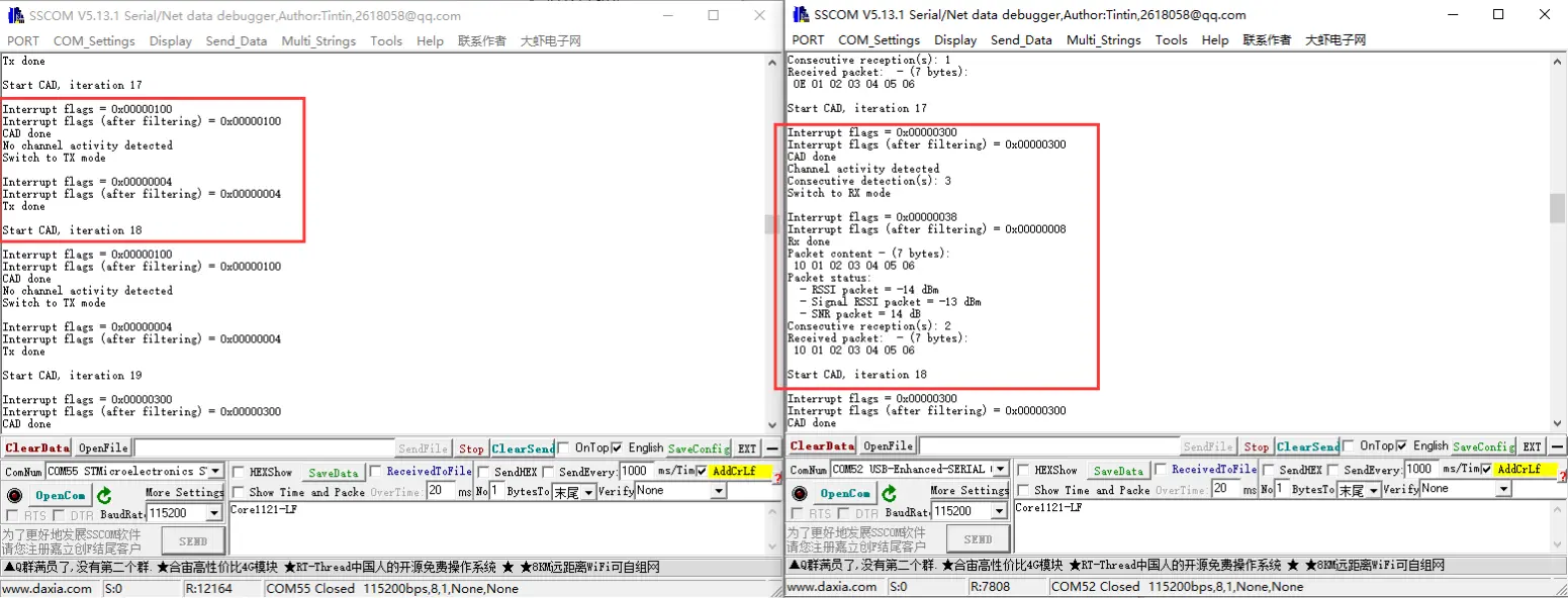
- This application will perform Channel Activity Detection (CAD) - LoRa only.
- Flash one device with CAD_EXIT_MODE set to TX, and another with CAD_EXIT_MODE set to RX to start testing.
- The effect is as follows:
lr1121_firmware_update
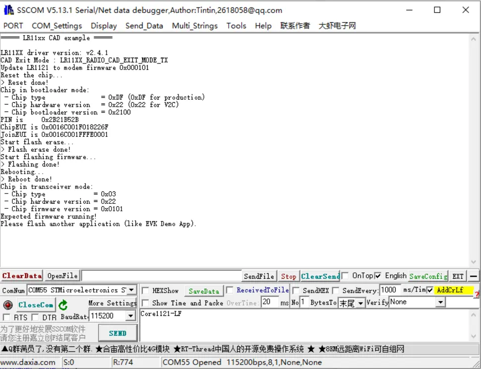
- This application will update the firmware on the LR1121.
- By default, it flashes the transceiver firmware version 0101. To test other firmware versions, comment out
#include "lr1121_transceiver_0101.h"inlr1121_firmware_update.hand uncomment other header files, then compile and flash. Only one firmware can be selected for flashing at a time. - The effect is as follows:
lr1121_lr_fhss
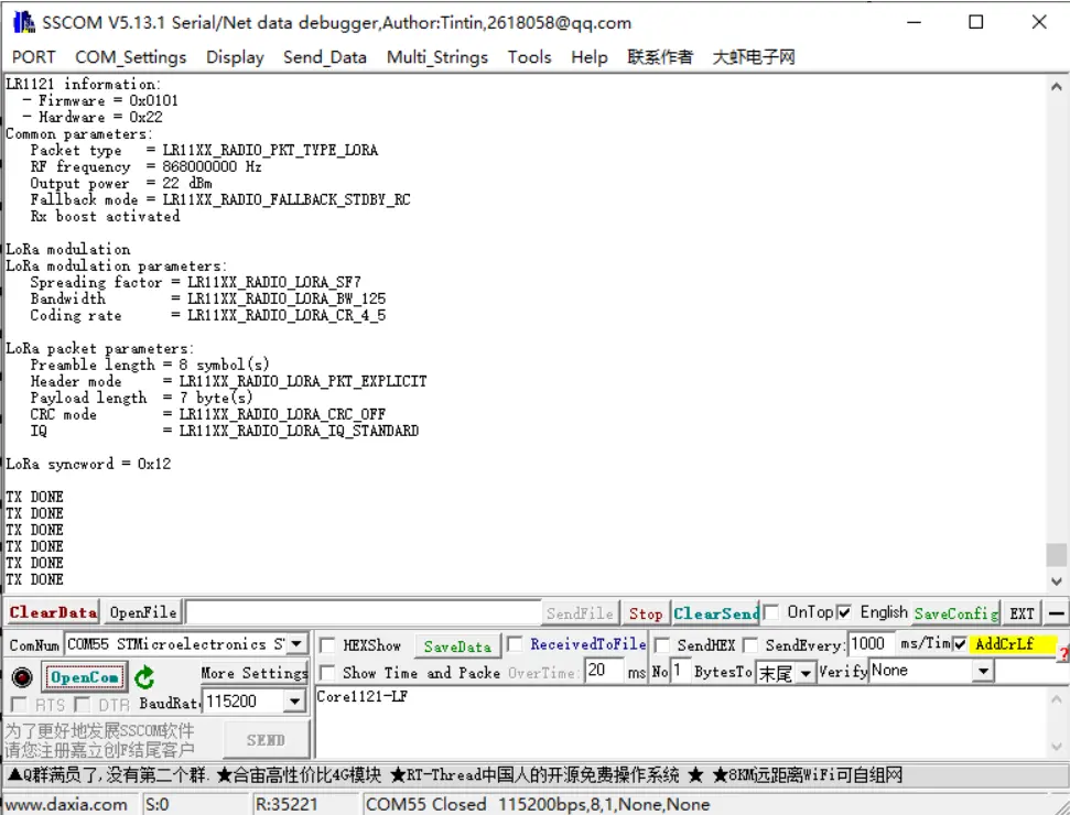
- This application will configure the device to transmit data packets in LR-FHSS mode.
- The effect is as follows:
lr1121_per
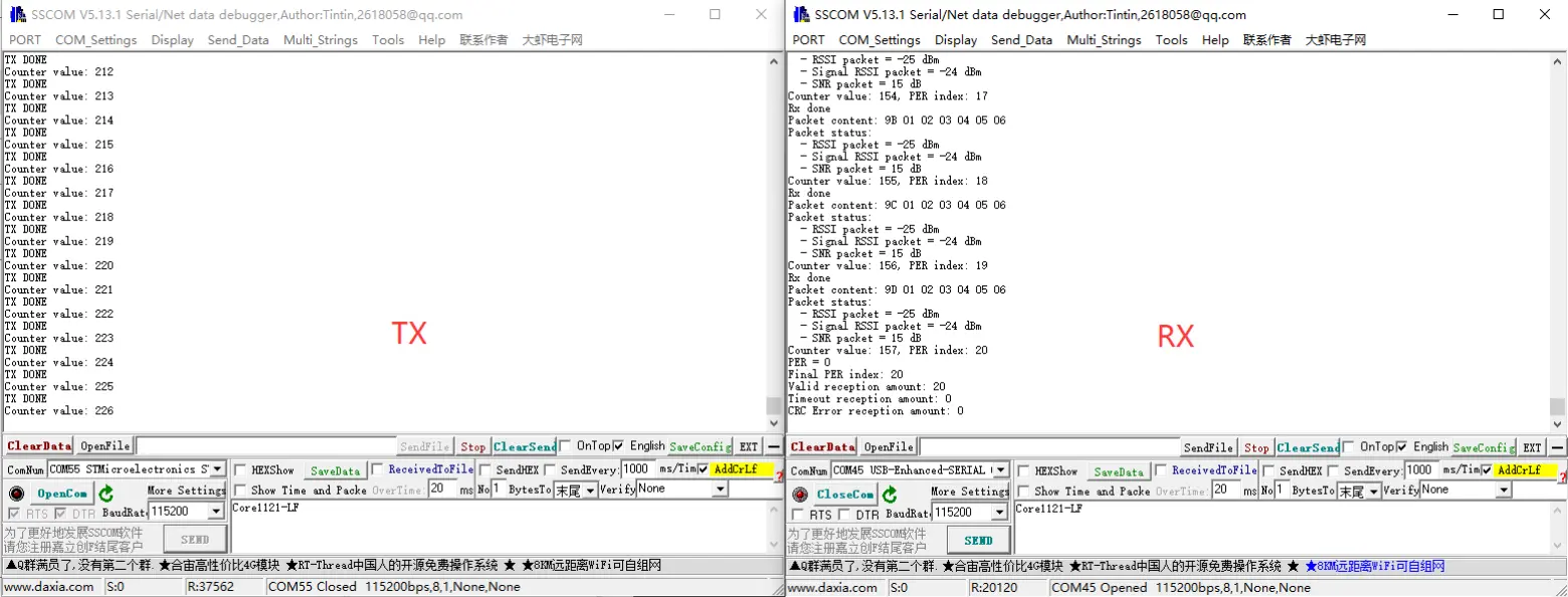
- PER (Packet Error Rate) test. In
lr1121_per.h, set one device as transmitter by defining#define RECEIVER 1, and set the other device as receiver by defining#define RECEIVER 0. - The effect is as follows:
lr1121_ping_pong
- This application sets the device to ping-pong mode (point-to-point bidirectional communication test).
- The effect is as follows:
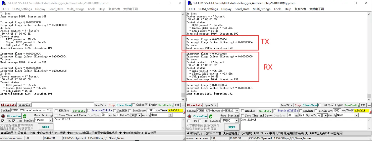
lr1121_read
- This application sets the device to read mode, automatically recognizing strings and hexadecimal numbers. Used with
lr1121_writeto achieve point-to-point communication. - The effect is as follows:
lr1121_write
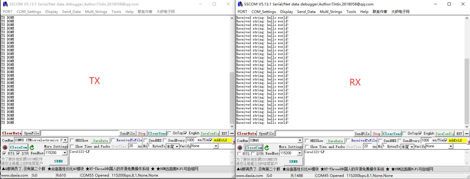
- This application sets the device to write mode, automatically sending data. Used with
lr1121_readto achieve point-to-point communication. - The effect is as follows:
lr1121_sigfox
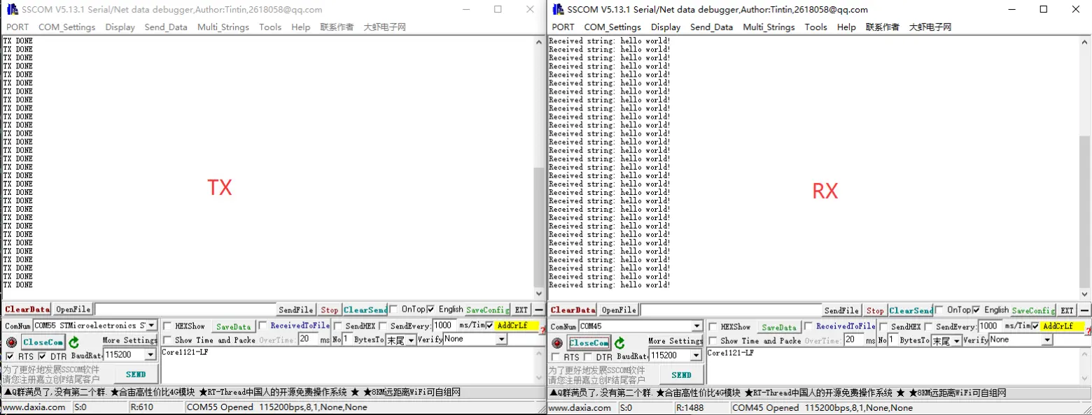
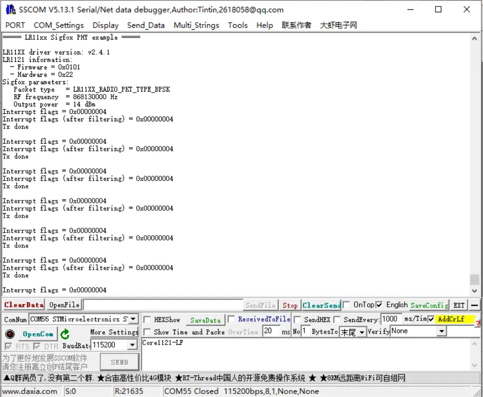
- This application configures the device to send Sigfox-compliant uplinks.
- The effect is as follows:
lr1121_spectral_scan
- This application implements spectrum scanning by setting the device to Rx continuous mode and periodically reading the instantaneous RSSI of each frequency channel.
- Can be tested in conjunction with
lr1121_tx_cw. - Use
lr1121_tx_cwto emit a signal at 868MHz with a power of 22dBm for testing. The results are as follows: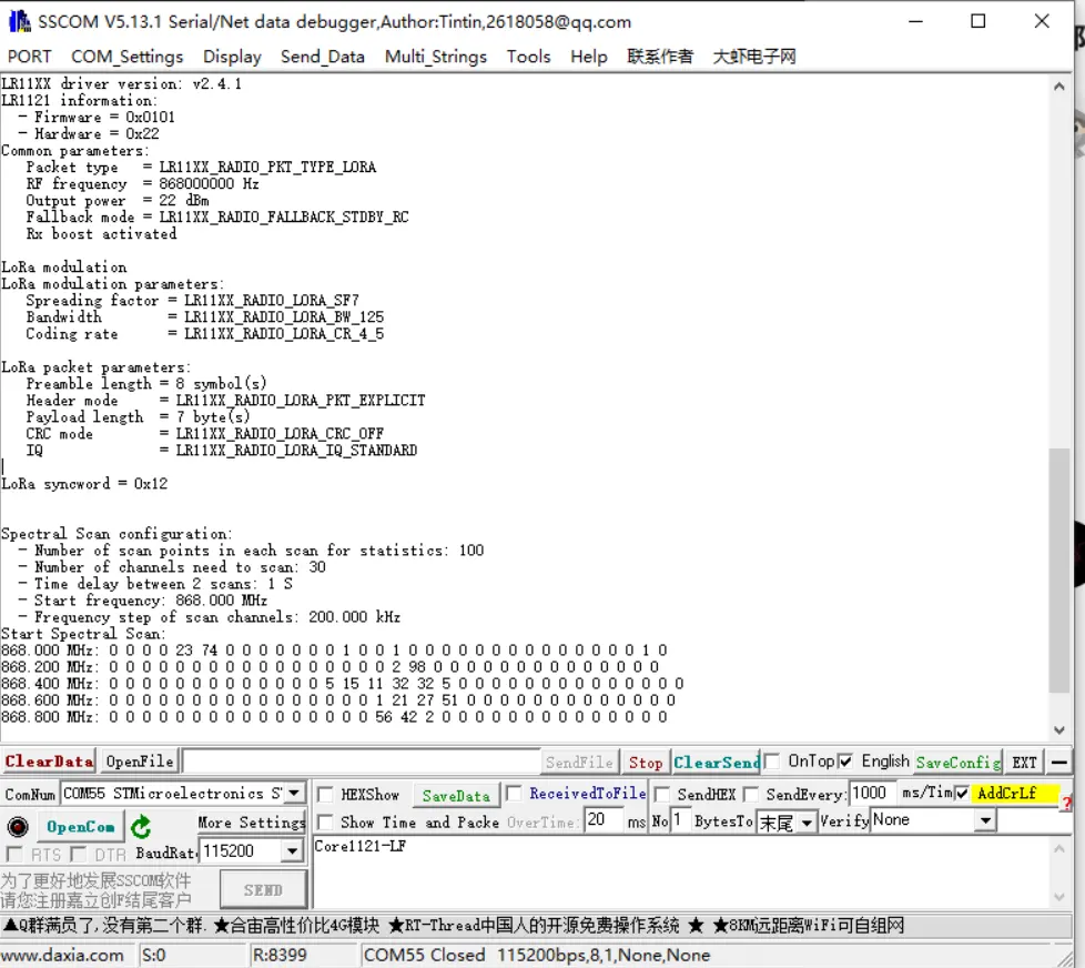
lr1121_spetrum_display
- This application implements spectrum display by setting the device to Rx continuous mode and periodically reading the instantaneous RSSI of each frequency channel.
- Can be tested in conjunction with
lr1121_tx_cw. - The plotting function requires support for VT100 control codes, e.g., MobaXterm.
- Use
lr1121_tx_cwto emit a signal at 868MHz with a power of 22dBm for testing. The results are as follows: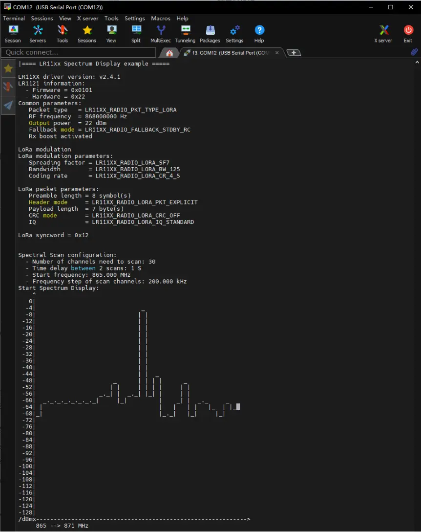
lr1121_tx_cw
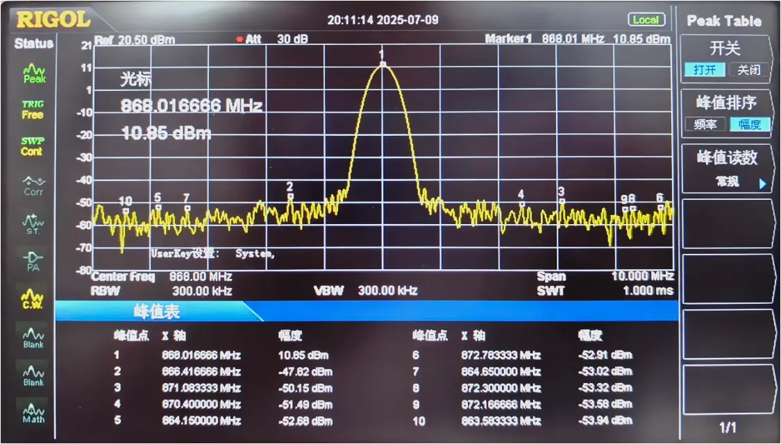
- This application configures the device to continuously transmit an unmodulated carrier wave.
- The effect is as follows:
lr1121_tx_infinite_preamble
- This application configures the device to continuously transmit an unmodulated carrier wave.
- It continuously transmits a waveform. This waveform is modulated (LoRa format), mainly used for testing LoRa transmission performance, spectrum, and certification (LoRa mode).
- Does not send a complete packet, but uses a valid LoRa preamble modulation.
LoRa and LoRaWAN
What is LoRa?
Semtech's LoRa is a long-range, low-power wireless platform for the Internet of Things (IoT). Generally, it refers to radio frequency chips using LoRa technology. Its main features are as follows:
LoRa (short for long range) uses a spread spectrum modulation technology derived from Chirp Spread Spectrum (CSS) technology. It is a type of long-distance wireless transmission technology and LPWAN communication technology. Spread spectrum technology trades bandwidth for sensitivity. Technologies like Wi-Fi and ZigBee also use spread spectrum, but LoRa modulation is characterized by approaching the Shannon-Hartley theorem limit, maximizing sensitivity improvement. Compared to traditional FSK technology, at the same communication rate, LoRa has 8~12 dBm better sensitivity than FSK. Currently, LoRa primarily operates in the Sub-GHz ISM bands.
LoRa technology integrates digital spread spectrum, digital signal processing, and forward error correction coding, significantly improving long-distance communication performance. LoRa's link budget is superior to any other standardized communication technology; the link budget is the main factor determining distance in a given environment.
LoRa RF chips mainly include the SX127X series, SX126X series, and SX130X series. The SX127X and SX126X series are used for LoRa nodes, while the SX130X series is used for LoRa gateways. For details, refer to Semtech's product list.
What is LoRaWAN?
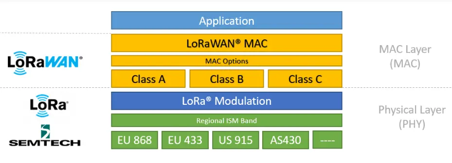
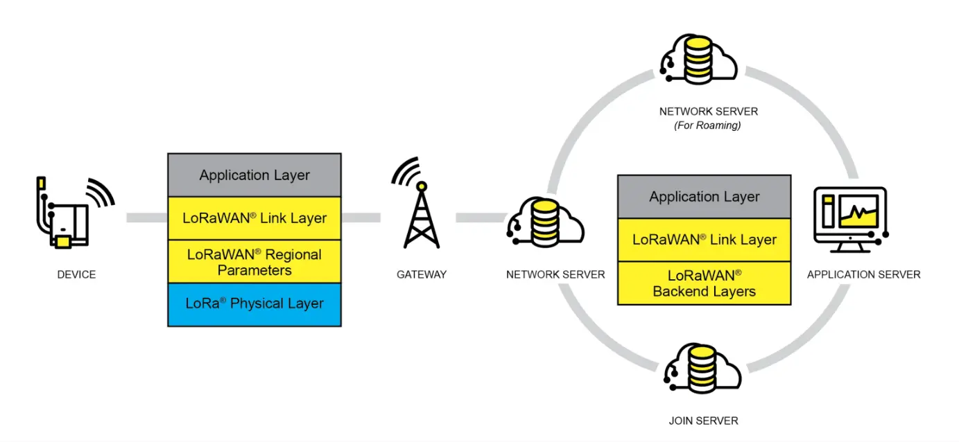
LoRaWAN is an open protocol for Low-Power Wide-Area Networks (LPWAN) built on top of the LoRa radio modulation technique. It is designed to wirelessly connect battery-powered "things" to the internet in regional, national, or global networks, targeting key IoT requirements such as bidirectional end-to-end communication, end-to-end security, mobility, and localization services. Nodes require network join authentication to connect wirelessly to the internet, establishing an encrypted communication channel between the node and the server. The LoRaWAN protocol layers are shown in the figure below.
The Class A/B/C node device types in the MAC layer cover almost all IoT application scenarios. The difference between them lies in the transmission and reception time slots of the nodes.
In the Modulation layer, parameters like EU868 and AS430 indicate different frequency bands used in different countries. Please refer to the link for regional parameters.
Implementing a LoRaWAN network covering a city or other area requires four components: nodes (LoRa node RF chips), gateways (or base stations, LoRa gateway RF chips), servers, and the cloud, as shown in the figure below.
A DEVICE (node device) must first initiate a join request packet to the GATEWAY and then to the server. Only after successful authentication can it normally send and receive application data with the server.
The GATEWAY can communicate with the server via wired networks or 3/4/5G wireless networks.
Major server-side operators include TTN, etc. For setting up your own cloud service, please refer to lorawan-stack or chirpstack.
Application
- This application is based on the official LoRaWAN example
ModemE_application_examplesand only demonstrates the basic LoRaWAN Class A application. Other advanced examples can be ported from the official repository, including: Join Request, LoRaWAN Class B application, LoRaWAN Multicast Class B/C examples, and FUOTA examples.
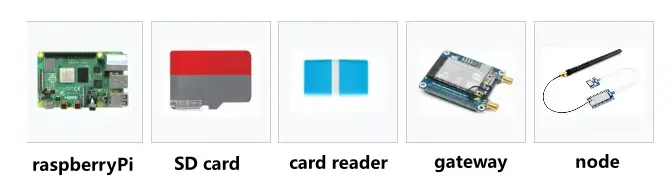
Component Preparation
Raspberry Pi 4B (with compatible power supply)
TF card (TF card with a capacity greater than 8GB is recommended)
Card reader
Gateway device
Node device
Development board (optional models): ESP32, Raspberry Pi, STM32, and Raspberry Pi Pico
Server Setup
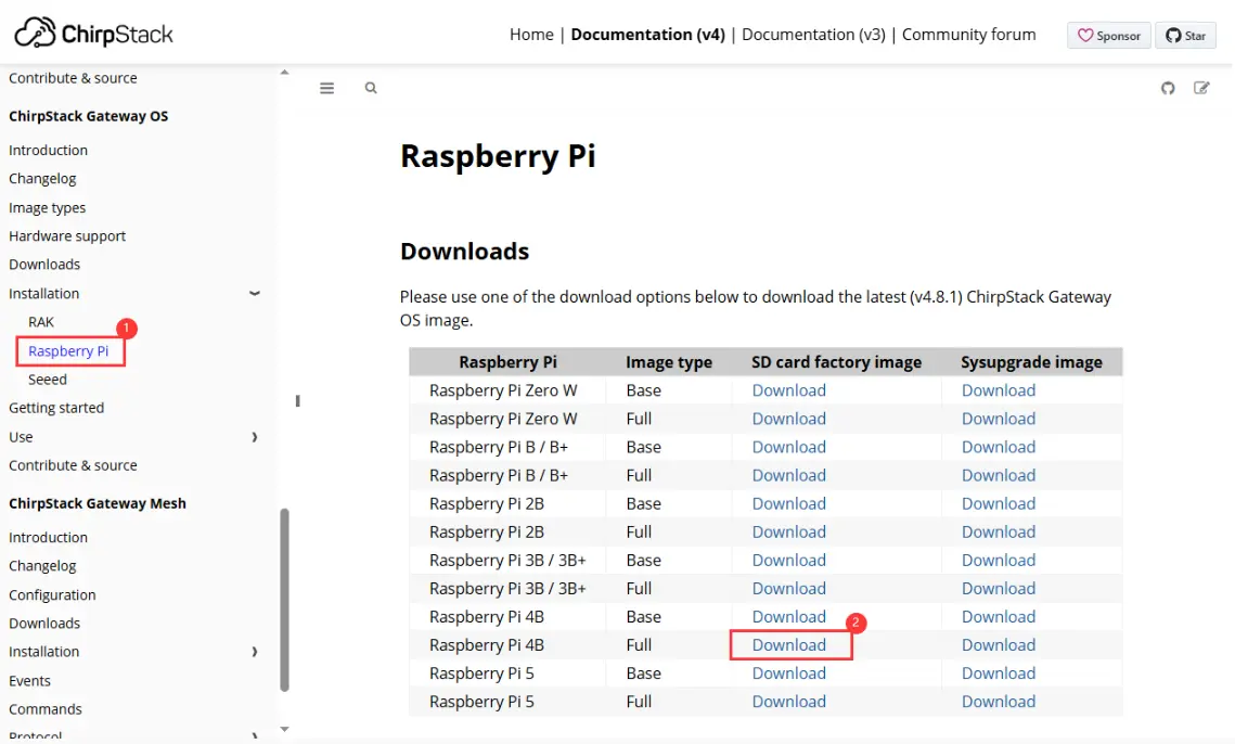
This example uses ChirpStack as the LoRaWAN network server. Please follow the official Raspberry Pi installation steps for configuration.
First, download the ChirpStack Gateway OS image, extract it, and use Win32DiskImager to write the image to the TF card.
Downloading the Image
Writing the Image
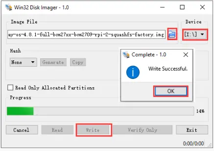
After writing, please refer to the official documentation for detailed configuration. This document only provides a brief installation guide. For details, see: ChirpStack Gateway OS Getting Started Guide.
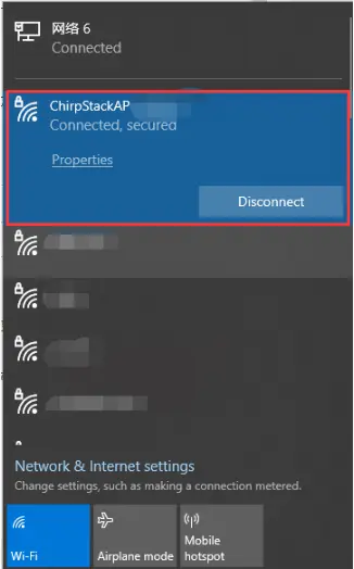
Insert the TF card into the Raspberry Pi and power it on. After booting, your computer's Wi-Fi should detect a wireless hotspot named
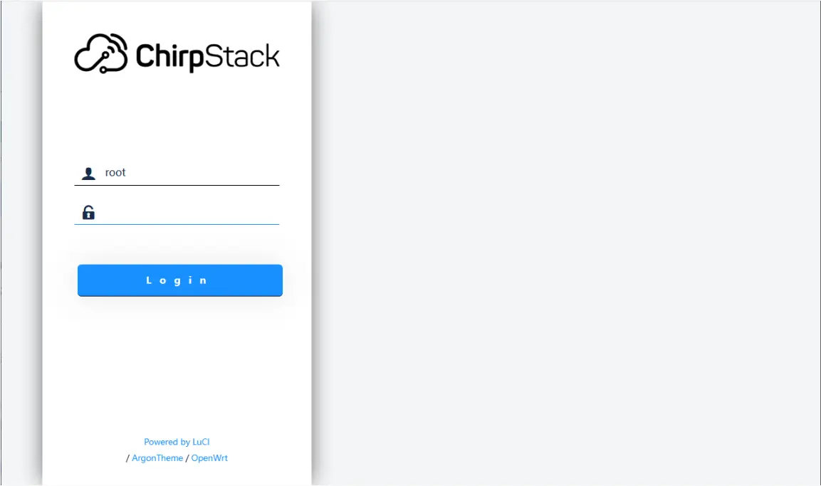
ChirpStackAP-XXXXXXwith the passwordChirpStackAP. After connecting successfully, access192.168.0.1in a browser to open the ChirpStack management interface. No password is required for the first login.Connecting to Wi-Fi
Accessing the Web Interface
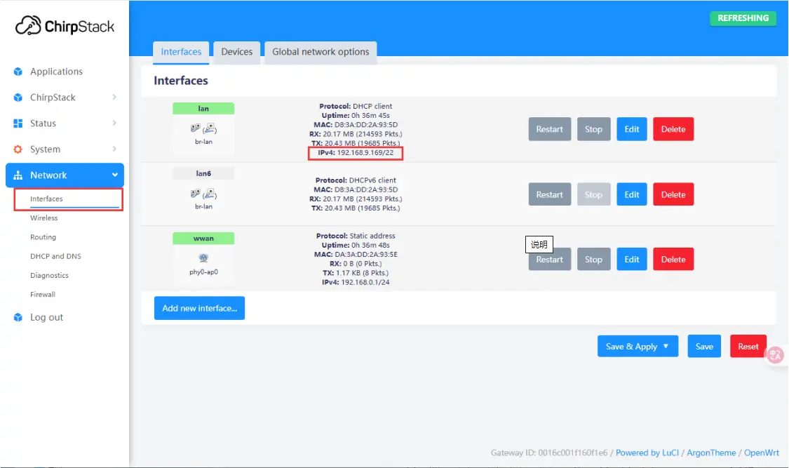
After booting, you can connect to an external network via Ethernet or Wi-Fi. Here, connecting via Ethernet is used as an example. To configure Wi-Fi, please refer to: Wi-Fi Configuration. After connecting to the network, you can view the current IP address in the web management interface.
Adding a Gateway
After the server configuration is complete and the IP address is obtained, power off the Raspberry Pi and disconnect the power. Connect the SX1303-868M-LoRaWAN-Gateway-HAT (gateway device) to the Raspberry Pi and attach the antenna. After powering on the Raspberry Pi, use the previously obtained IP address to remotely access the device via an SSH tool (such as MobaXterm). The default username is
root. After a successful connection, enter the following command in the terminal to get the gateway ID:gateway-id. The system will output the current device's gateway ID. Make a note of this ID; it will be needed when adding the gateway later.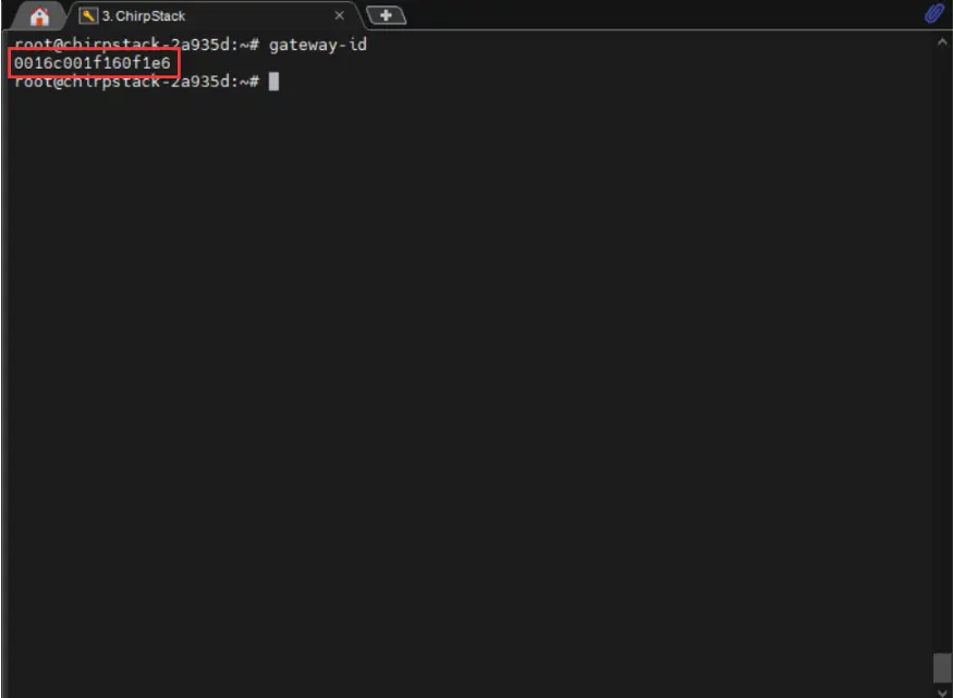
Enter the previously obtained IP address in a browser to access the ChirpStack management interface. Navigate to ChirpStack -> Concentratord and enable the gateway function. Using the SX1303 (868 MHz) as an example, configure it as shown below, then click "Save & Apply":
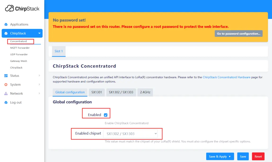
Enabling the Gateway
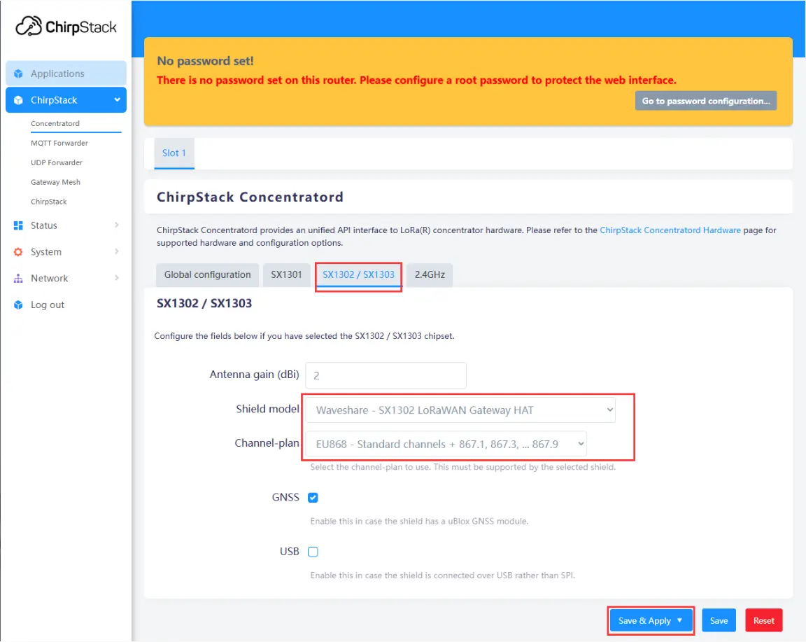
Configuring Gateway Parameters
Navigate to Applications -> ChirpStack. The first time you enter, you need to log in. The default username and password are both
admin. After logging in, click Gateways -> Add gateway, fill in the gateway-id obtained earlier on the Add page, and save it. Return to the Gateway page to see if the gateway has been successfully launched.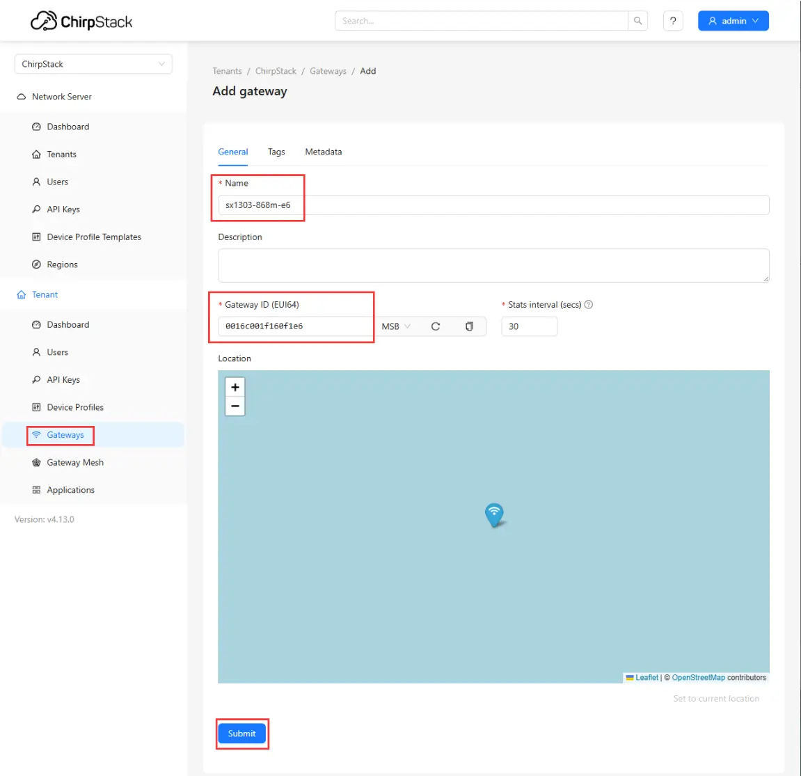
Adding Gateway to Server
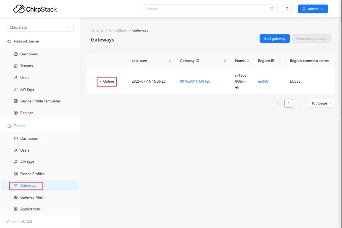
Checking if Gateway is Online
Adding a Node
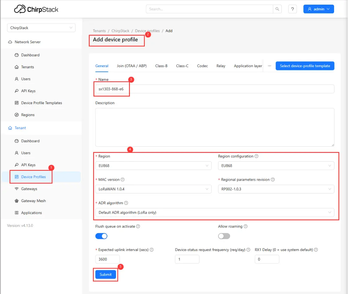
First, add a device profile in the web interface: Device Profiles -> Add device profile. Configure as shown in the figure below:
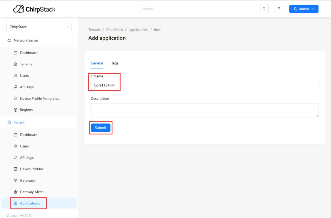
Then, add an application: Applications -> Add application, fill in the relevant information, and save:
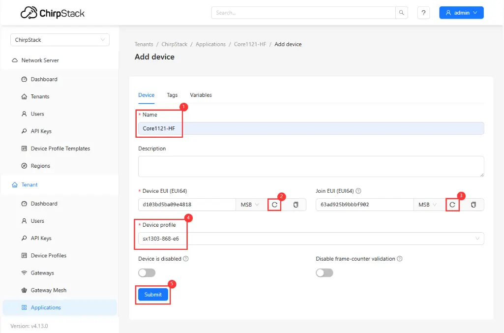
Setting EUI
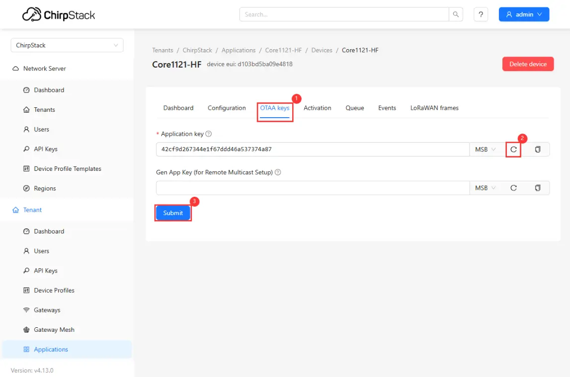
Setting Key
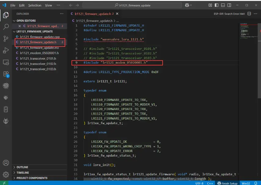
Note: The ESP32-S3-LR1121 module operates in transceiver mode by default. To run the LoRaWAN protocol, you must first flash the corresponding firmware via the development board. Refer to the
lr1121_firmware_updateexample in the Demo and run lr1121_firmware_update + lr1121_modem_05020001.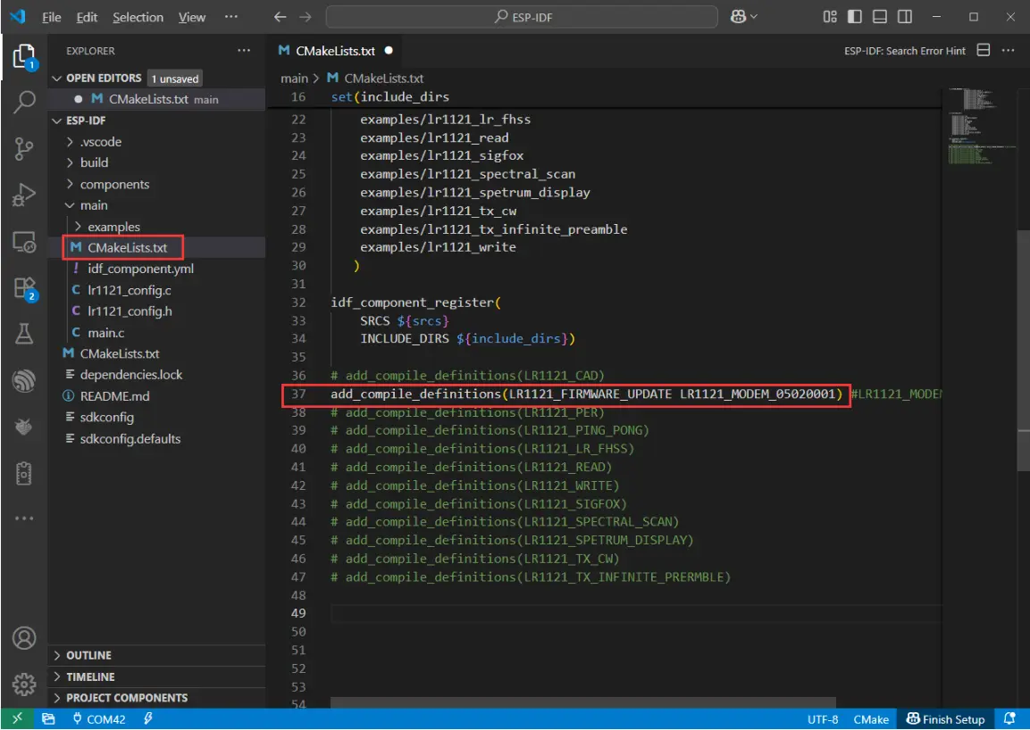
ESP-IDF Demo
Arduino ESP32 Demo
The effect after successful flashing is shown below:
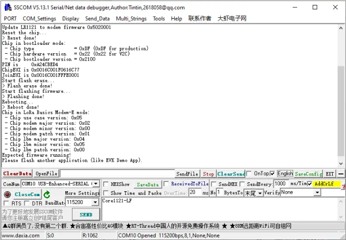
If you need to restore transceiver mode (non-LoRaWAN) later, please re-flash the
lr1121_transceiver_0101firmware.After the firmware is flashed, download the LoRaWAN example program. Open it and navigate to the directory
ESP32-S3-LR1121\esp32s3\ESP-IDF\main\examples\lr1121_LoRaWAN. Edit thelorawan_commissioning.hfile and fill in the previously generated EUI, key, and other information in the corresponding positions. After completion, compile and flash.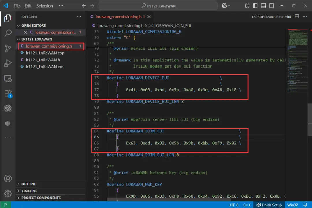
Filling in EUI
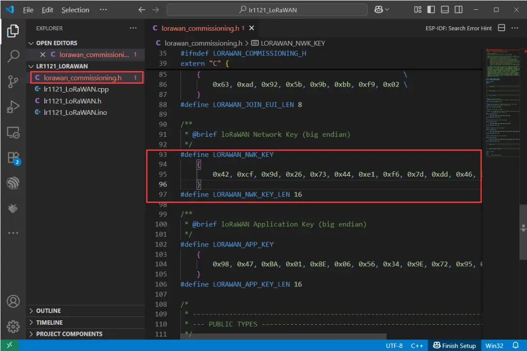
Filling in Key
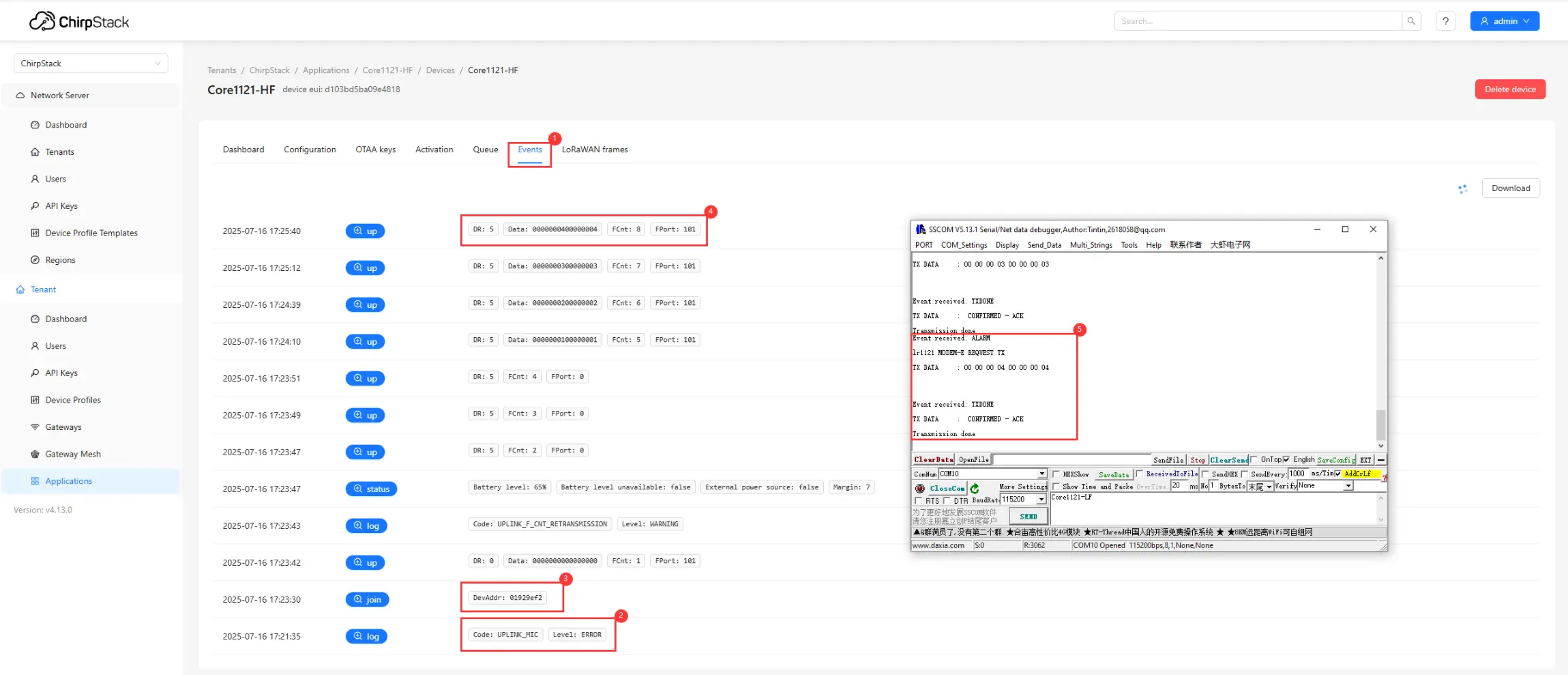
After flashing, the node will automatically request to join the LoRaWAN network. Upon successful joining, the node will periodically send uplink data. You can view device events and communication status through the web interface:
①. Click Events to view the node's operating status.
②. Check for join failures.
③. If joining is successful, you can see the join event.
④. View the data reported by the node.
⑤. View debug information via the serial port.
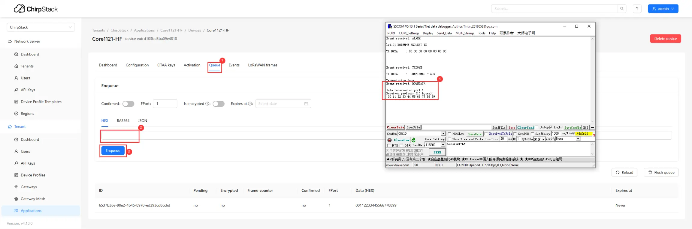
The server also supports sending downlink data to the node:
①. Click Queue.
②. Enter the hexadecimal data to be sent.
③. Click Send.
④. The node receives the data and prints it on the serial port.
Working with ESP-IDF
This chapter includes the following sections:
ESP-IDF Getting Started
New to ESP32 ESP-IDF development and looking to get started quickly? We have prepared a general Getting Started Tutorial for you.
- Section 1: Environment Setup
- Section 2: Running Examples
- Section 3: Creating a Project
- Section 4: Using Components
- Section 5: Debugging
- Section 6: FreeRTOS
- Section 7: Peripherals
- Section 8: Wi-Fi Programming
- Section 9: BLE Programming
Please Note: This tutorial uses the ESP32-S3-Zero as a teaching example, and all hardware code is based on its pinout. Before you start, it is recommended that you check the pinout of your development board to ensure the pin configuration is correct.
Setting Up Development Environment
The following guide uses Windows as an example, demonstrating development using VS Code + the ESP-IDF extension. macOS and Linux users should refer to the official documentation.
The screenshots in this section use ESP-IDF V5.5.2 as an example. When installing, please select the ESP-IDF version that matches your board's example.
Install the ESP-IDF Development Environment
Download the installation manager from the ESP-IDF Installation Manager page. This is Espressif's latest cross-platform installer. The following steps demonstrate how to use its offline installation feature.
Click the Offline Installer tab on the page, then select Windows as the operating system and the ESP-IDF version you need (the version shown in the screenshot is for reference only — choose the version that fits your actual needs).
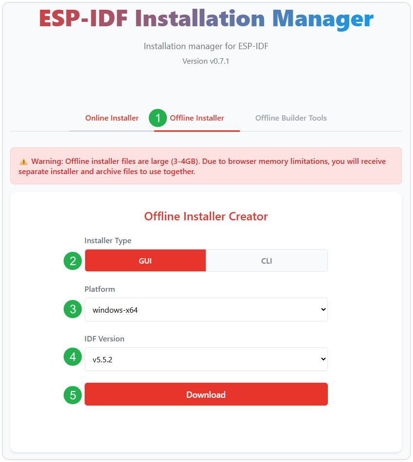
After confirming your selection, click the download button. The browser will automatically download two files: the ESP-IDF Offline Package (.zst) and the ESP-IDF Installer (.exe).
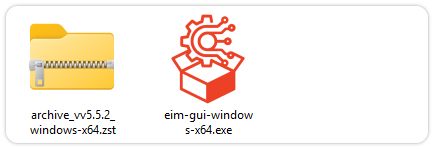
Please wait for both files to finish downloading.
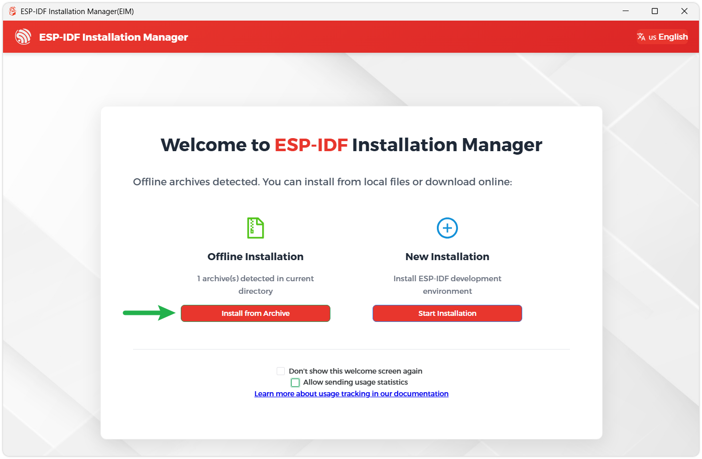
Once the download is complete, double-click to run the ESP-IDF Installer (eim-gui-windows-x64.exe).
The installer will automatically detect if the offline package exists in the same directory. Click Install from archive.
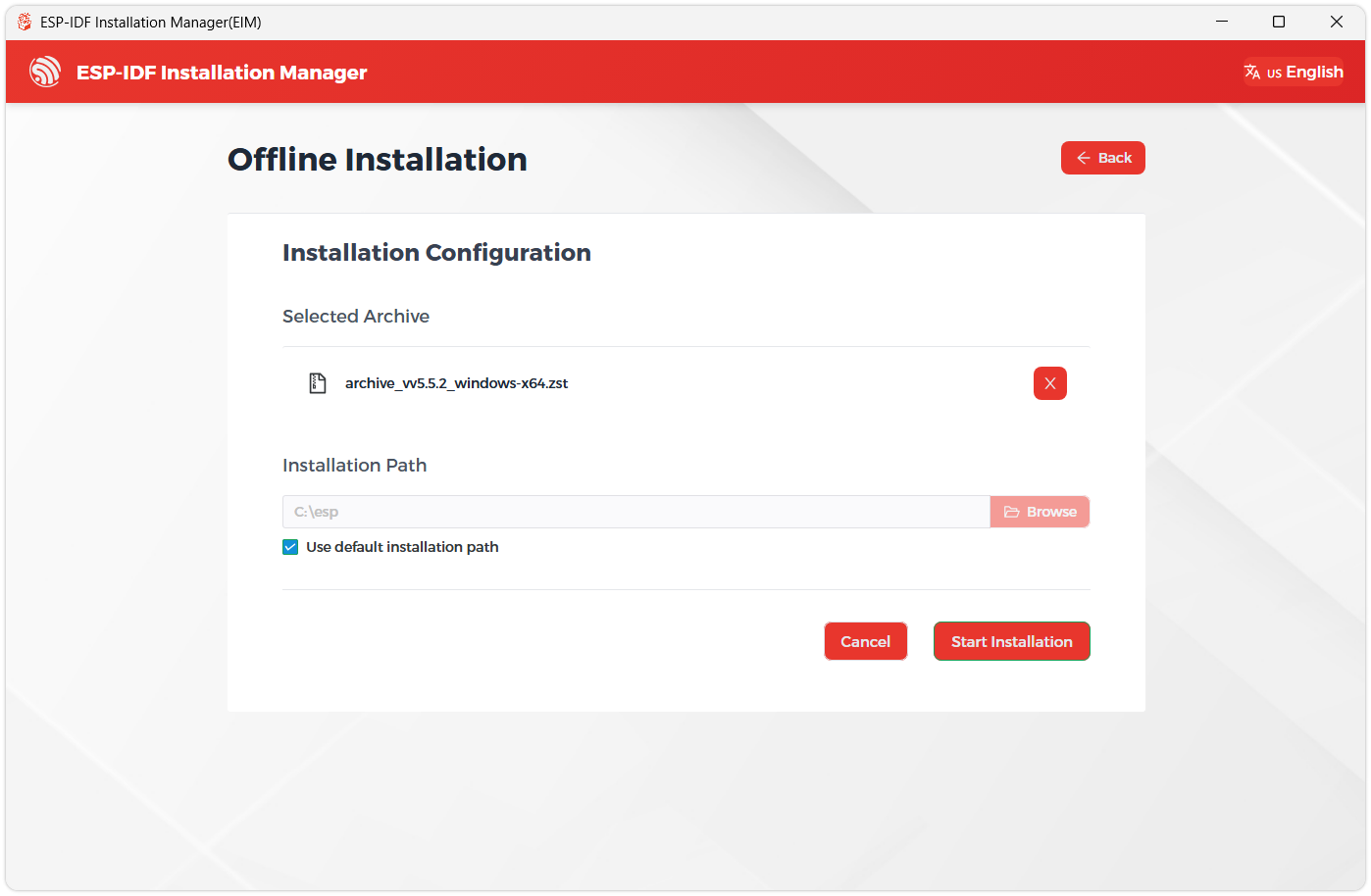
Next, select the installation path. We recommend using the default path. If you need to customize it, ensure the path does not contain Chinese characters or spaces. Click Start installation to proceed.
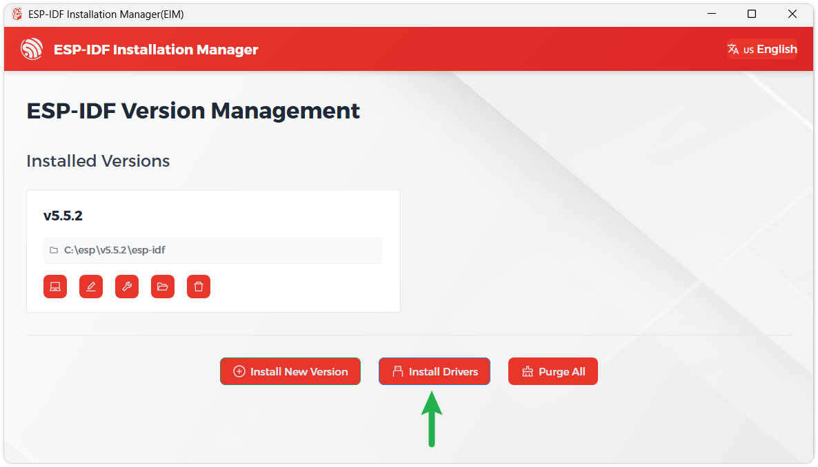
When you see the following screen, the ESP-IDF installation is successful.
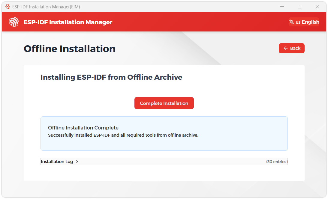
We recommend installing the drivers as well. Click Finish installation, then select Install driver.
Install Visual Studio Code and the ESP-IDF Extension
Download and install Visual Studio Code.
During installation, it is recommended to check Add "Open with Code" action to Windows Explorer file context menu to facilitate opening project folders quickly.
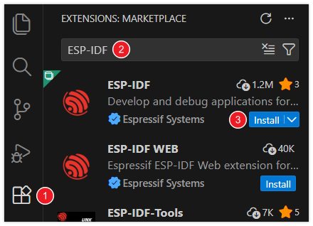
In VS Code, click the Extensions icon
 in the Activity Bar on the side (or use the shortcut Ctrl + Shift + X) to open the Extensions view.
Enter ESP-IDF in the search box, locate the ESP-IDF extension, and click Install.
For ESP-IDF extension versions ≥ 2.0, the extension will automatically detect and recognize the ESP-IDF environment installed in the previous steps, requiring no manual configuration.
Example
The example programs are located in the ESP-IDF directory of the example package: ESP32-S3-LR1121-XF-Demo.zip
The following example names align with the directory structure of the ESP32-S3-LR1121-XF example package, allowing for quick location of corresponding functionalities:
| Demo | Basic Description |
|---|---|
| lr1121_cad | Perform Channel Activity Detection (CAD) - LoRa only |
| lr1121_firmware_update | LR1121 firmware update tool |
| lr1121_lr_fhss | Transmit LR-FHSS data packets |
| lr1121_per | Perform Packet Error Rate (PER) test — Tx and Rx roles |
| lr1121_ping_pong | Initiate data exchange between two devices |
| lr1121_read | Enter receive mode |
| lr1121_sigfox | Send Sigfox-compliant uplink |
| lr1121_spectral_scan | Obtain inst-RSSI values in Rx mode to form a heatmap |
| lr1121_spetrum_display | Obtain inst-RSSI values in Rx mode to form a dynamic spectrum curve |
| lr1121_tx_cw | Tx Continuous Wave mode |
| lr1121_tx_infinite_preamble | Transmit infinite preamble |
| lr1121_write | Send data periodically |
| lr1121_LoRaWAN | Simple LoRaWAN Class A application |
Example Framework
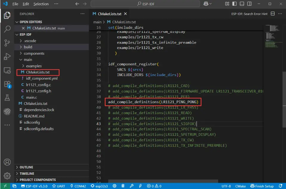
Download the examples, navigate to ESP32-S3-LR1121/esp32s3/ESP-IDF, and open the example using VS Code. Using ESP-IDF examples requires configuring the script file ESP32-S3-LR1121/esp32s3/ESP-IDF/main/CMakeLists.txt. It defaults to the lr1121_ping_pong example. To use other examples, uncomment the corresponding line as shown in the figure below:
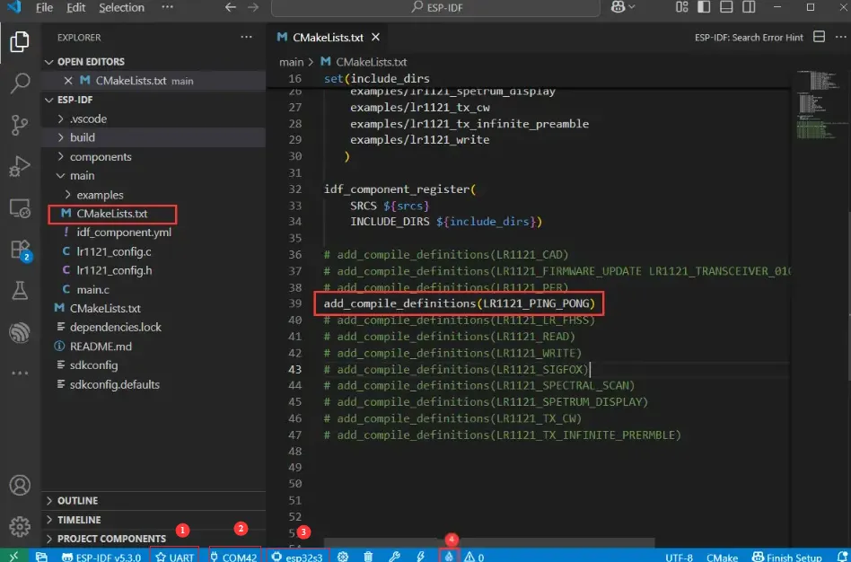
Once the environment is set up, select the correct board and port. If you are unsure how to flash, refer to the image below:
①. Select UART ②. Select Port ③. Select Chip ④. Compile and Flash
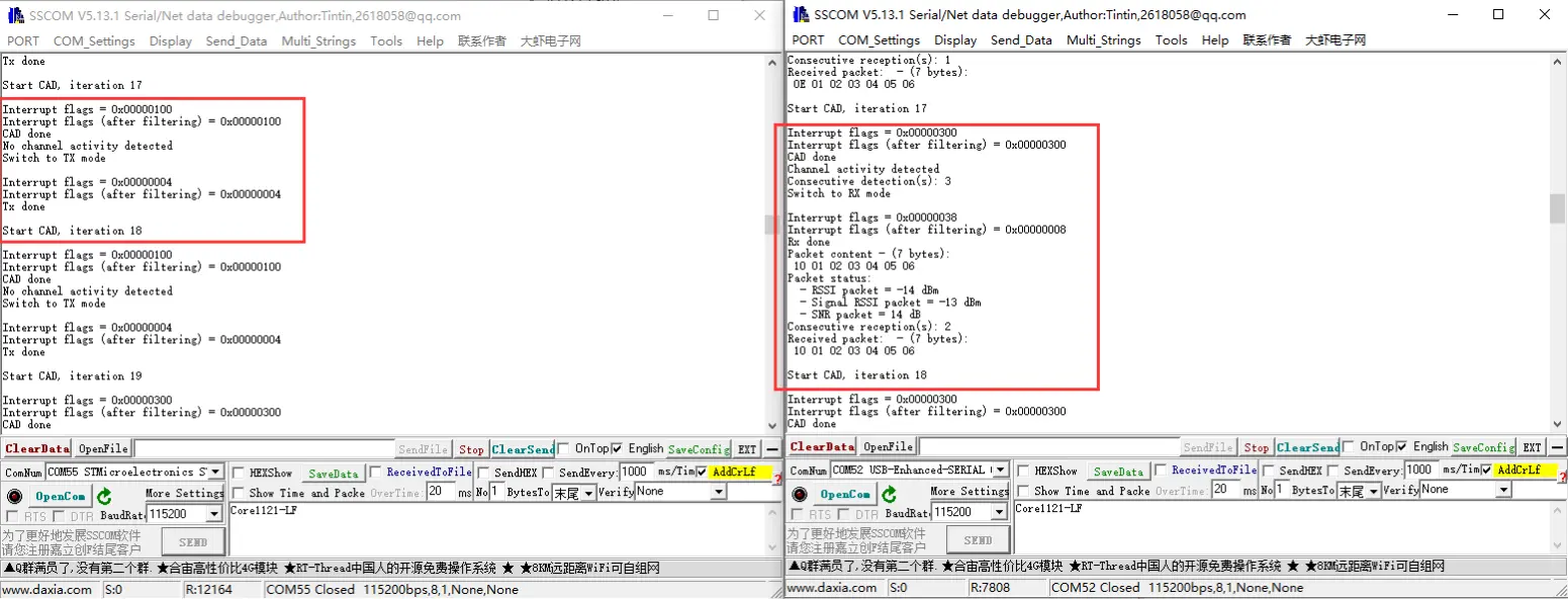
lr1121_cad
- This application will perform Channel Activity Detection (CAD) - LoRa only.
- Flash one device with CAD_EXIT_MODE set to TX, and another with CAD_EXIT_MODE set to RX to start testing.
- The effect is as follows:
lr1121_firmware_update
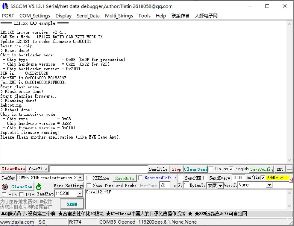
- By default, it flashes the transceiver firmware version 0101. To test other firmware versions, comment out
#include "lr1121_transceiver_0101.h"inlr1121_firmware_update.hand uncomment other header files, then compile and flash. Only one firmware can be selected for flashing at a time. - The effect is as follows:
lr1121_lr_fhss
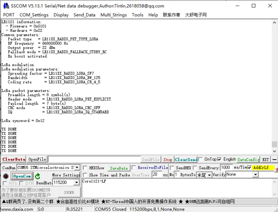
- This application will configure the device to transmit data packets in LR-FHSS mode.
- The effect is as follows:
lr1121_per
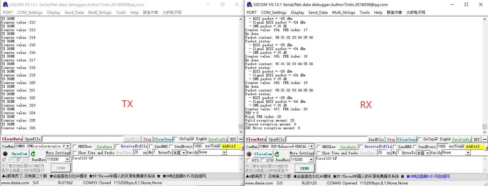
- PER (Packet Error Rate) test. In
lr1121_per.h, set one device as transmitter by defining#define RECEIVER 1, and set the other device as receiver by defining#define RECEIVER 0. - The effect is as follows:
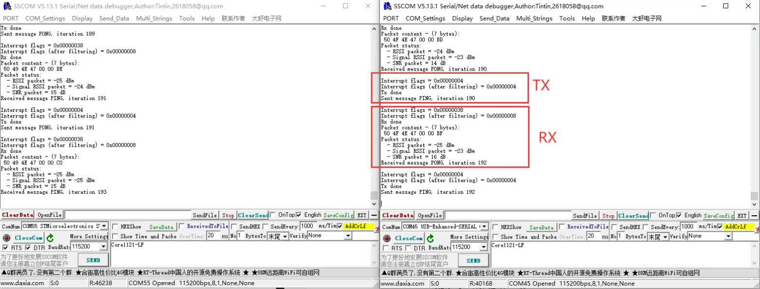
lr1121_ping_pong
- This application sets the device to ping-pong mode (point-to-point bidirectional communication test).
- The effect is as follows:
lr1121_read
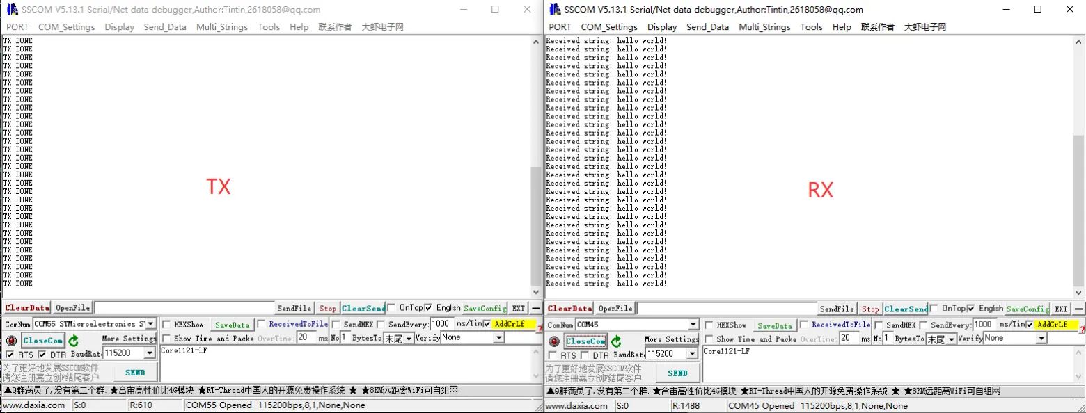
- This application sets the device to read mode, automatically recognizing strings and hexadecimal numbers. Used with
lr1121_writeto achieve point-to-point communication. - The effect is as follows:
lr1121_write
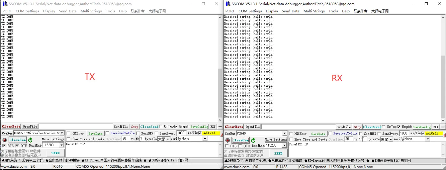
- This application sets the device to write mode, automatically sending data. Used with
lr1121_readto achieve point-to-point communication. - The effect is as follows:
lr1121_sigfox
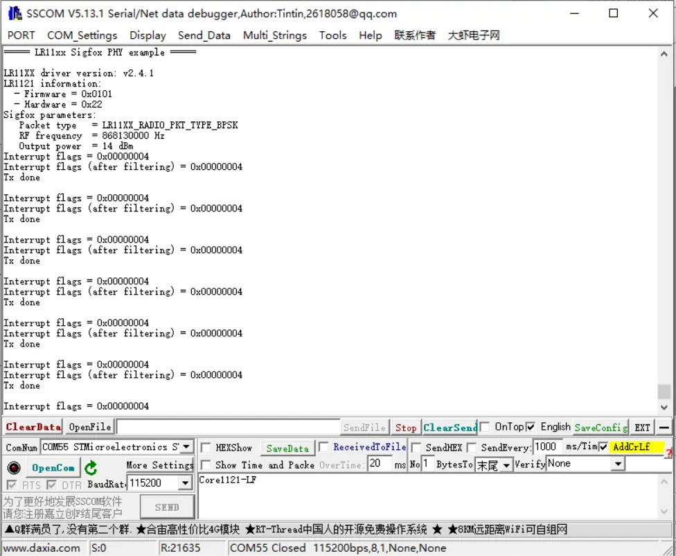
- This application configures the device to send Sigfox-compliant uplinks.
- The effect is as follows:
lr1121_spectral_scan
- This application implements spectrum scanning by setting the device to Rx continuous mode and periodically reading the instantaneous RSSI of each frequency channel.
- Can be tested in conjunction with
lr1121_tx_cw. - Use
lr1121_tx_cwto emit a signal at 868MHz with a power of 22dBm for testing. The results are as follows: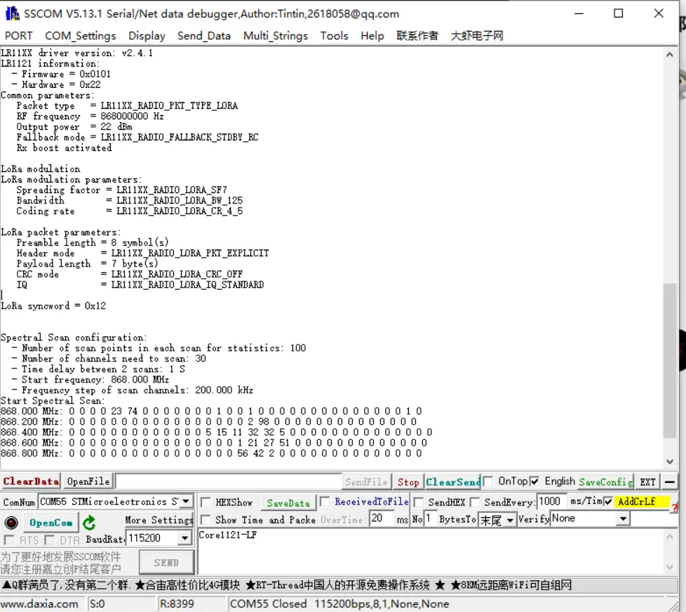
lr1121_spetrum_display
- This application implements spectrum display by setting the device to Rx continuous mode and periodically reading the instantaneous RSSI of each frequency channel.
- Can be tested in conjunction with
lr1121_tx_cw. - The plotting function requires support for VT100 control codes, e.g., MobaXterm.
- Use
lr1121_tx_cwto emit a signal at 868MHz with a power of 22dBm for testing. The results are as follows: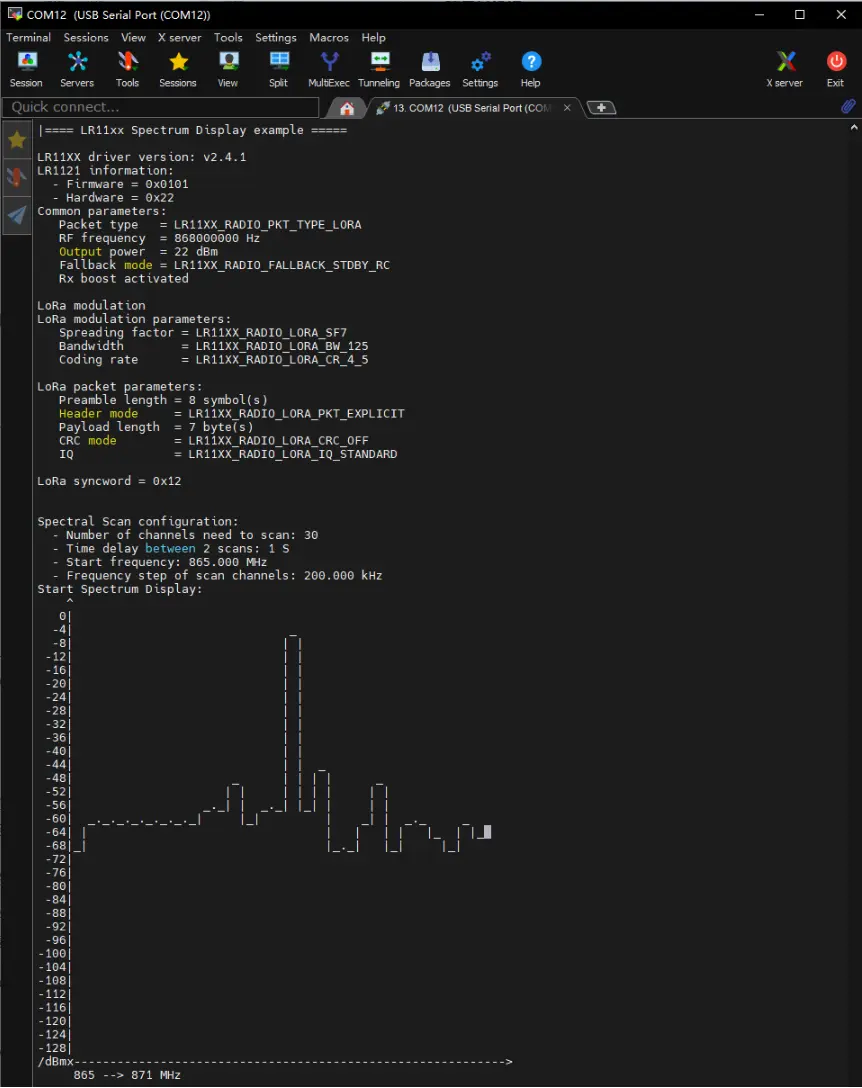
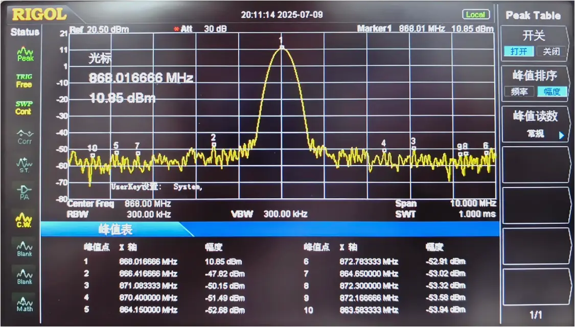
lr1121_tx_cw
- This application configures the device to continuously transmit an unmodulated carrier wave.
- The effect is as follows:
lr1121_tx_infinite_preamble
- This application configures the device to continuously transmit an unmodulated carrier wave.
- It continuously transmits a waveform. This waveform is modulated (LoRa format), mainly used for testing LoRa transmission performance, spectrum, and certification (LoRa mode).
- Does not send a complete packet, but uses a valid LoRa preamble modulation.
LoRa and LoRaWAN
What is LoRa?
Semtech's LoRa is a long-range, low-power wireless platform for the Internet of Things (IoT). Generally, it refers to radio frequency chips using LoRa technology. Its main features are as follows:
- LoRa (short for long range) uses a spread spectrum modulation technology derived from Chirp Spread Spectrum (CSS) technology. It is a type of long-distance wireless transmission technology and LPWAN communication technology. Spread spectrum technology trades bandwidth for sensitivity. Technologies like Wi-Fi and ZigBee also use spread spectrum, but LoRa modulation is characterized by approaching the Shannon-Hartley theorem limit, maximizing sensitivity improvement. Compared to traditional FSK technology, at the same communication rate, LoRa has 8~12 dBm better sensitivity than FSK. Currently, LoRa primarily operates in the Sub-GHz ISM bands.
- LoRa technology integrates digital spread spectrum, digital signal processing, and forward error correction coding, significantly improving long-distance communication performance. LoRa's link budget is superior to any other standardized communication technology; the link budget is the main factor determining distance in a given environment.
- LoRa RF chips mainly include the SX127X series, SX126X series, and SX130X series. The SX127X and SX126X series are used for LoRa nodes, while the SX130X series is used for LoRa gateways. For details, refer to Semtech's product list.
What is LoRaWAN?
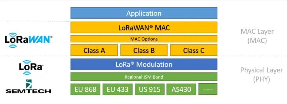
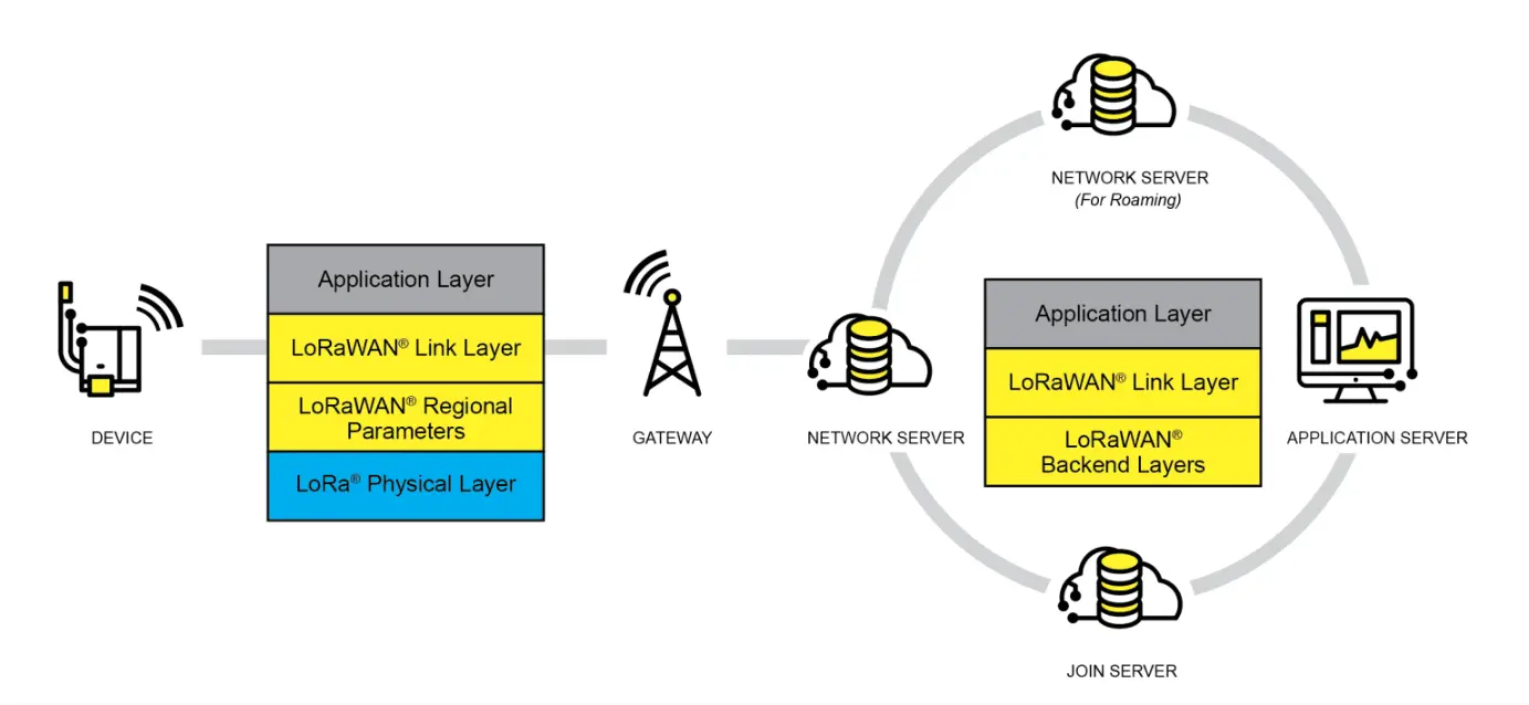
LoRaWAN is an open protocol for Low-Power Wide-Area Networks (LPWAN) built on top of the LoRa radio modulation technique. It is designed to wirelessly connect battery-powered "things" to the internet in regional, national, or global networks, targeting key IoT requirements such as bidirectional end-to-end communication, end-to-end security, mobility, and localization services. Nodes require network join authentication to connect wirelessly to the internet, establishing an encrypted communication channel between the node and the server. The LoRaWAN protocol layers are shown in the figure below.
The Class A/B/C node device types in the MAC layer cover almost all IoT application scenarios. The difference between them lies in the transmission and reception time slots of the nodes.
In the Modulation layer, parameters like EU868 and AS430 indicate different frequency bands used in different countries. Please refer to the link for regional parameters.
Implementing a LoRaWAN network covering a city or other area requires four components: nodes (LoRa node RF chips), gateways (or base stations, LoRa gateway RF chips), servers, and the cloud, as shown in the figure below.
A DEVICE (node device) must first initiate a join request packet to the GATEWAY and then to the server. Only after successful authentication can it normally send and receive application data with the server.
The GATEWAY can communicate with the server via wired networks or 3/4/5G wireless networks.
Major server-side operators include TTN, etc. For setting up your own cloud service, please refer to lorawan-stack or chirpstack.
Application
- This application is based on the official LoRaWAN example
ModemE_application_examplesand only demonstrates the basic LoRaWAN Class A application. Other advanced examples can be ported from the official repository, including: Join Request, LoRaWAN Class B application, LoRaWAN Multicast Class B/C examples, and FUOTA examples.
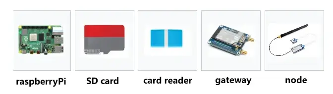
Component Preparation
Raspberry Pi 4B (with compatible power supply)
TF card (TF card with a capacity greater than 8GB is recommended)
Card reader
Gateway device
Node device
Development board (optional models): ESP32, Raspberry Pi, STM32, and Raspberry Pi Pico
Server Setup
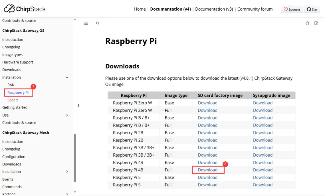
This example uses ChirpStack as the LoRaWAN network server. Please follow the official Raspberry Pi installation steps for configuration.
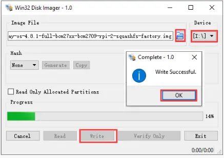
First, download the ChirpStack Gateway OS image, extract it, and use Win32DiskImager to write the image to the TF card.
Downloading the Image
Writing the Image
After writing, please refer to the official documentation for detailed configuration. This document only provides a brief installation guide. For details, see: ChirpStack Gateway OS Getting Started Guide.
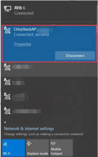
Insert the TF card into the Raspberry Pi and power it on. After booting, your computer's Wi-Fi should detect a wireless hotspot named
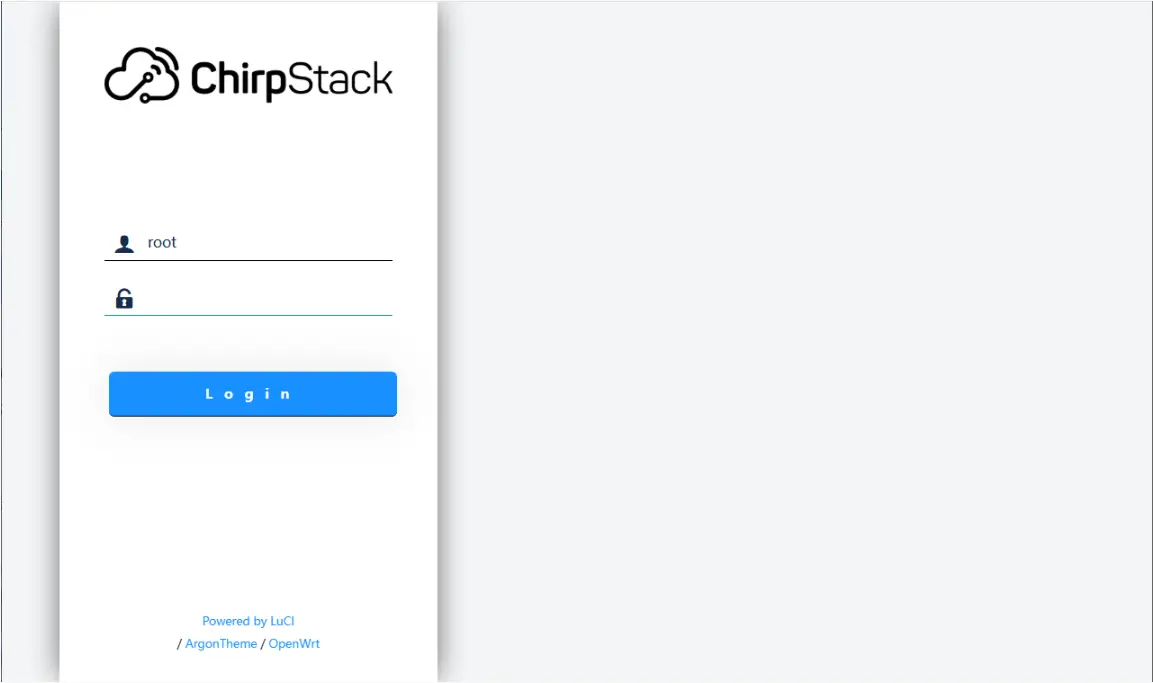
ChirpStackAP-XXXXXXwith the passwordChirpStackAP. After connecting successfully, access192.168.0.1in a browser to open the ChirpStack management interface. No password is required for the first login.Connecting to Wi-Fi
Accessing the Web Interface
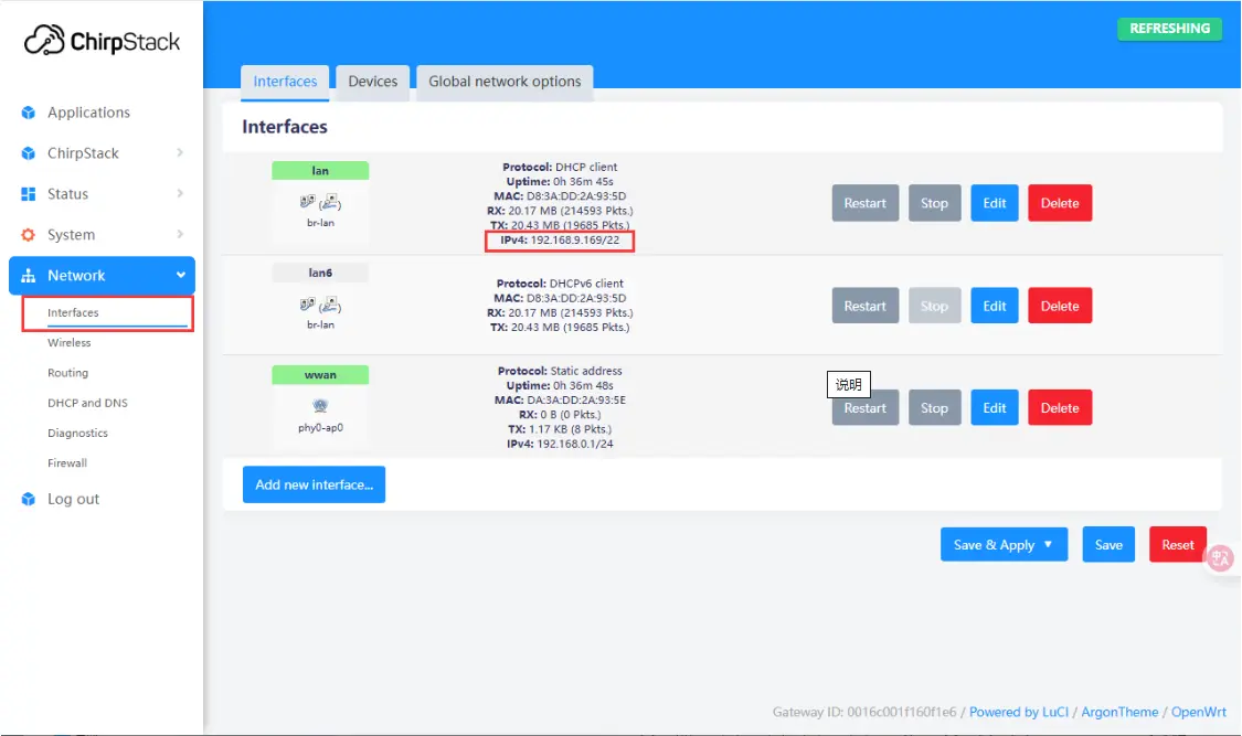
After booting, you can connect to an external network via Ethernet or Wi-Fi. Here, connecting via Ethernet is used as an example. To configure Wi-Fi, please refer to: Wi-Fi Configuration. After connecting to the network, you can view the current IP address in the web management interface.
Adding a Gateway
After the server configuration is complete and the IP address is obtained, power off the Raspberry Pi and disconnect the power. Connect the SX1303-868M-LoRaWAN-Gateway-HAT (gateway device) to the Raspberry Pi and attach the antenna. After powering on the Raspberry Pi, use the previously obtained IP address to remotely access the device via an SSH tool (such as MobaXterm). The default username is
root. After a successful connection, enter the following command in the terminal to get the gateway ID:gateway-id. The system will output the current device's gateway ID. Make a note of this ID; it will be needed when adding the gateway later.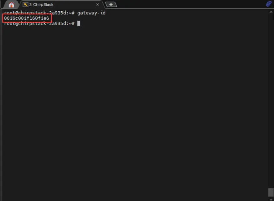
Enter the previously obtained IP address in a browser to access the ChirpStack management interface. Navigate to ChirpStack -> Concentratord and enable the gateway function. Using the SX1303 (868 MHz) as an example, configure it as shown below, then click "Save & Apply":
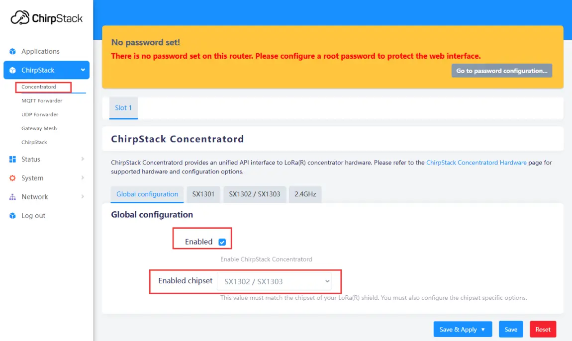
Enabling the Gateway
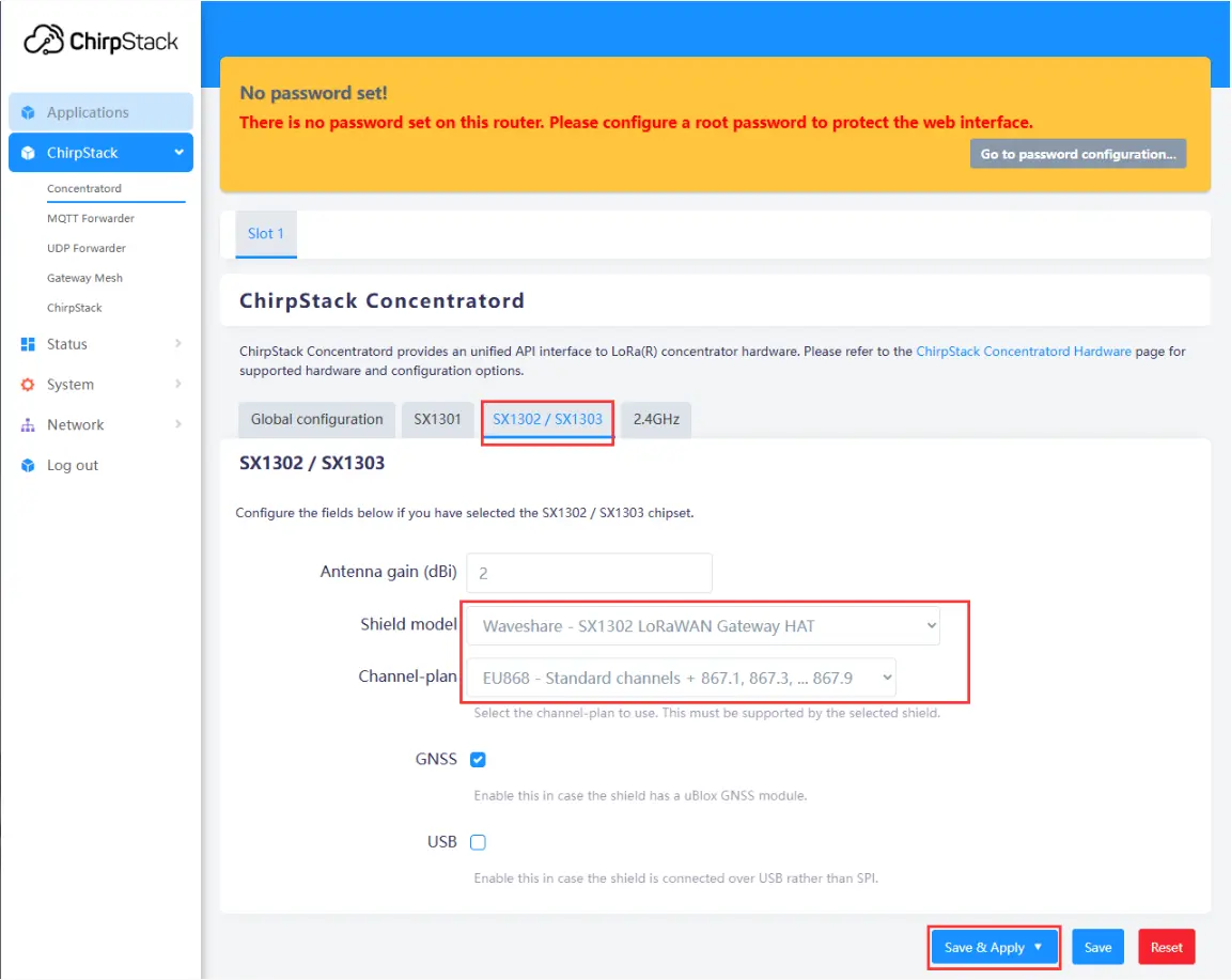
Configuring Gateway Parameters
Navigate to Applications -> ChirpStack. The first time you enter, you need to log in. The default username and password are both
admin. After logging in, click Gateways -> Add gateway, fill in the gateway-id obtained earlier on the Add page, and save it. Return to the Gateway page to see if the gateway has been successfully launched.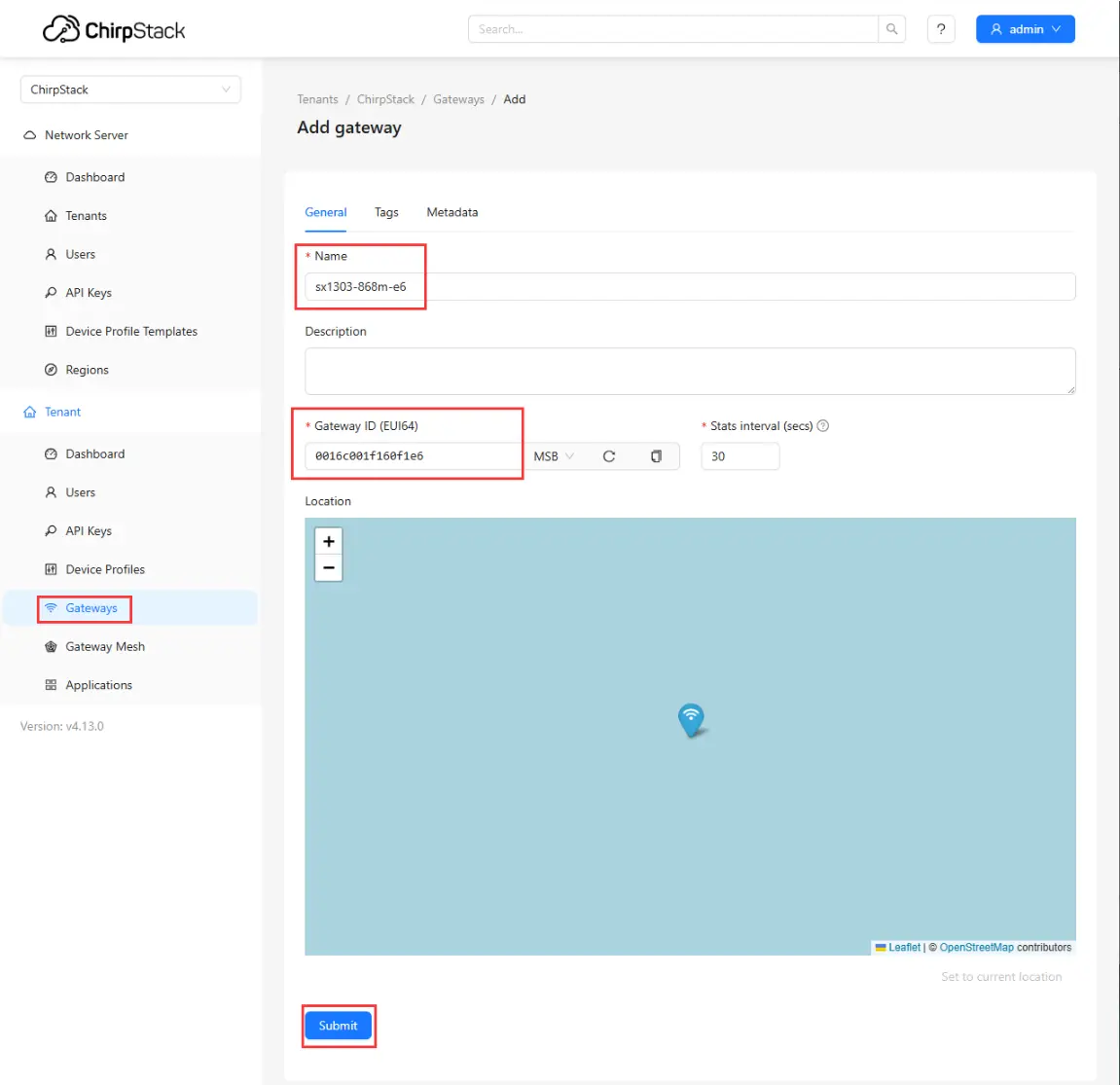
Adding Gateway to Server
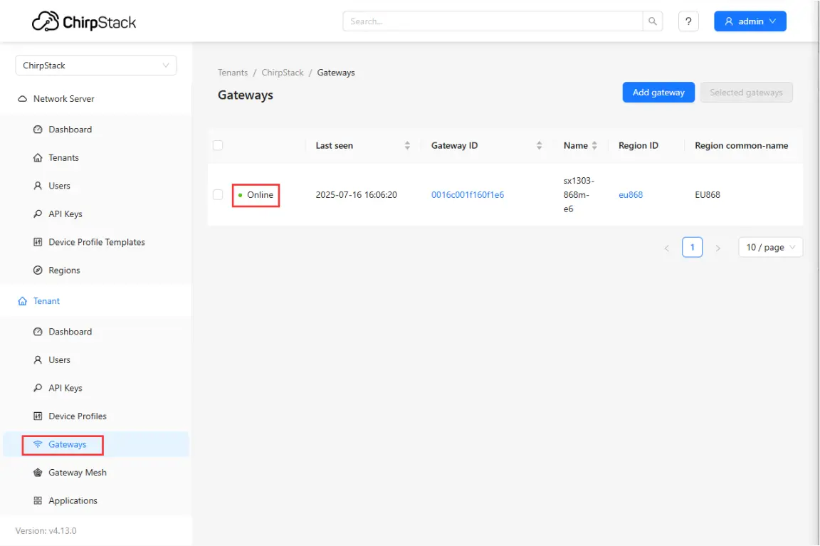
Checking if Gateway is Online
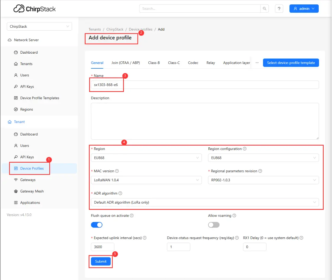
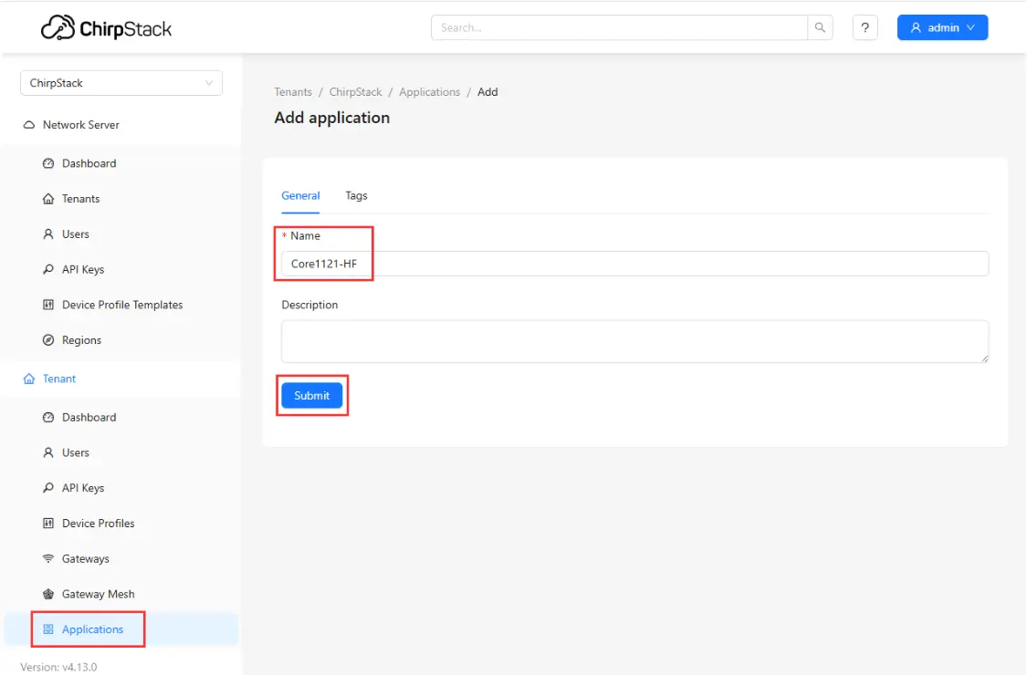
Adding a Node
First, add a device profile in the web interface: Device Profiles -> Add device profile. Configure as shown in the figure below:
Then, add an application: Applications -> Add application, fill in the relevant information, and save:
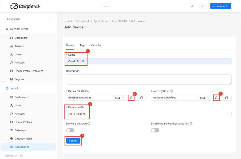
Setting EUI
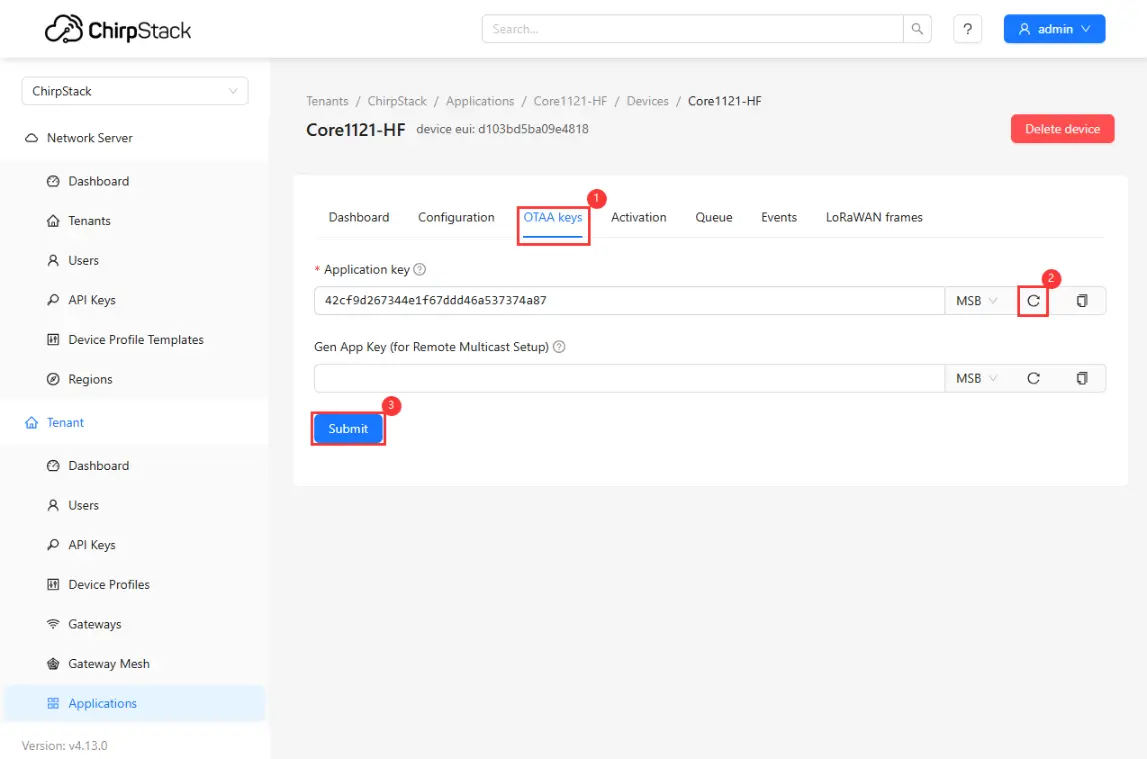
Setting Key
Note: The ESP32-S3-LR1121 module operates in transceiver mode by default. To run the LoRaWAN protocol, you must first flash the corresponding firmware via the development board. Refer to the
lr1121_firmware_updateexample in the Demo and run lr1121_firmware_update + lr1121_modem_05020001.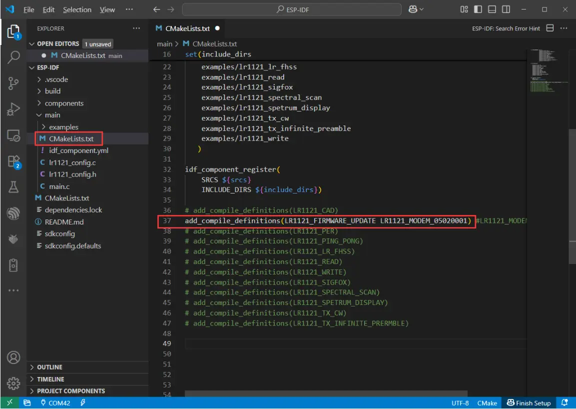
ESP-IDF Demo
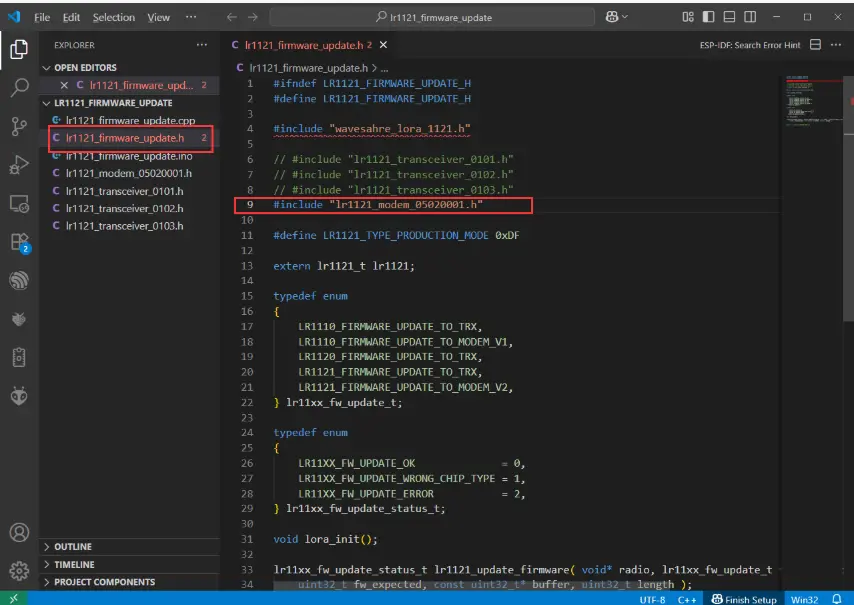
Arduino ESP32 Demo
The effect after successful flashing is shown below:
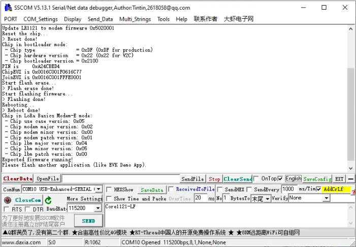
If you need to restore transceiver mode (non-LoRaWAN) later, please re-flash the
lr1121_transceiver_0101firmware.After the firmware is flashed, download the LoRaWAN example program. Open it and navigate to the directory
ESP32-S3-LR1121\esp32s3\ESP-IDF\main\examples\lr1121_LoRaWAN. Edit thelorawan_commissioning.hfile and fill in the previously generated EUI, key, and other information in the corresponding positions. After completion, compile and flash.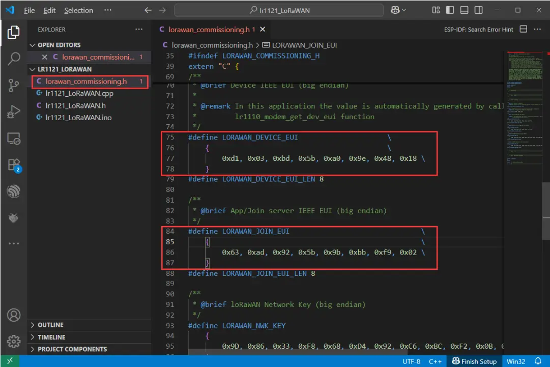
Filling in EUI
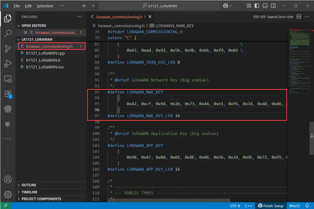
Filling in Key
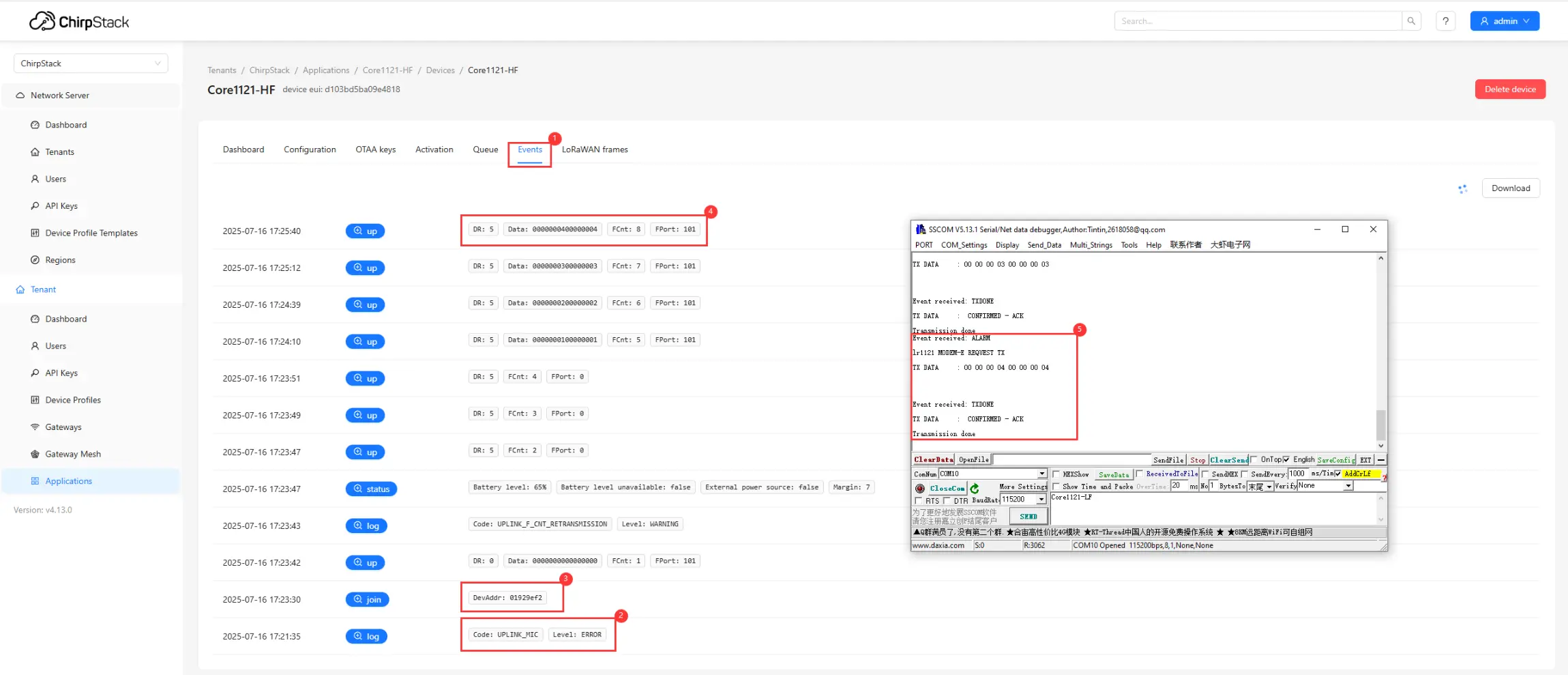
After flashing, the node will automatically request to join the LoRaWAN network. Upon successful joining, the node will periodically send uplink data. You can view device events and communication status through the web interface:
①. Click Events to view the node's operating status.
②. Check for join failures.
③. If joining is successful, you can see the join event.
④. View the data reported by the node.
⑤. View debug information via the serial port.
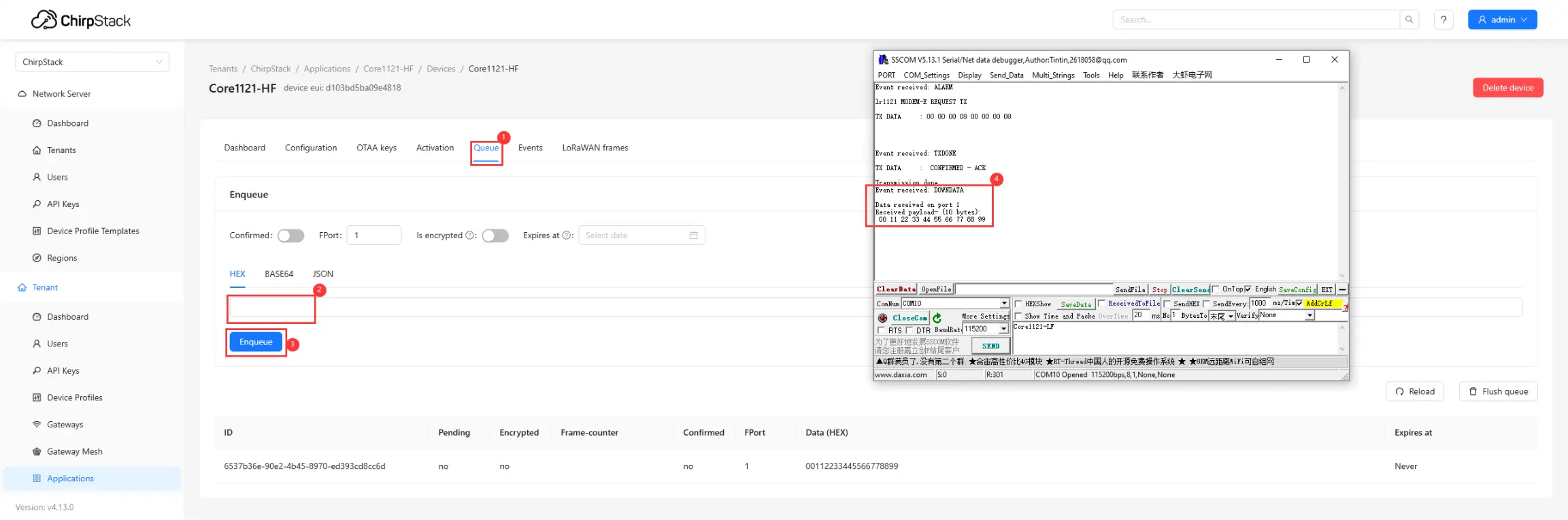
The server also supports sending downlink data to the node:
①. Click Queue.
②. Enter the hexadecimal data to be sent.
③. Click Send.
④. The node receives the data and prints it on the serial port.
Meshtastic Tutorial
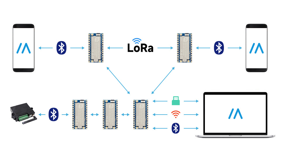
Meshtastic® is an open-source project that utilizes LoRa technology to achieve long-distance, low-power, off-grid mesh network communication. Leveraging its powerful ESP32-S3 dual-core processor and Semtech LR1121 RF chip, the ESP32-S3-LR1121 can perfectly run the Meshtastic firmware, providing you with a reliable outdoor communication solution.
1. Features
- Mesh Networking: Each node acts as both an endpoint and a repeater, automatically finding paths to extend communication range.
- Ultra-long Range: Utilizing LoRa modulation technology, it can achieve communication over several kilometers in line-of-sight conditions.
- Low Power Consumption: Designed for battery power, suitable for outdoor hiking, expeditions, rescue missions, etc.
- Multi-platform Support: Provides Android, iOS, Web, and desktop clients to interact with the device via serial, Bluetooth, or Wi-Fi.
- High Security: Supports AES-256 encryption to ensure the privacy of communication data.
- Off-grid Maps: When paired with a mobile app, it enables location sharing and off-grid map navigation.
2. Hardware Preparation
- ESP32-S3-LR1121*2: Development boards
- Antenna: Please ensure the antenna is connected before powering on; otherwise, the RF chip may be damaged.
- USB Type-C Data Cable*2: For firmware flashing.
3. Firmware Flashing
It is recommended to use the official Meshtastic Web Flasher for a simple and quick process.
We also provide pre-compiled firmware, which you can find in Waveshare's ESP32-S3-LR1121 Resource Package.
Enter Flashing Mode:
- Connect the development board to your computer using a USB data cable.
- Press and hold the onboard BOOT button.
- Press the RST button once.
- Release the BOOT button.
- The device should now enter download mode.
Using the Web Flasher:
- Access the Meshtastic Web Flasher using Chrome or Edge browser.
- Click Connect and select the corresponding serial port.
- In the firmware selection list, look for firmware versions that support ESP32-S3 and LR1121.
- Note: If the official list does not yet contain dedicated firmware for this model, please refer to the pre-compiled firmware in the resource package.
- Select the latest stable version and click Flash to start the process.
Wait for Completion:
- After flashing is complete, the device will automatically restart.
4. Device Management and Configuration
Meshtastic offers three primary management methods: Web Interface (suitable for in-depth configuration), App Interface (ideal for daily mobile use), and CLI (for advanced developers).
4.1 Web Interface Configuration (Bluetooth/USB/HTTP)
If you connect the device to your computer via USB, or if the device is connected via Bluetooth, you can use the Web configurator for intuitive management.
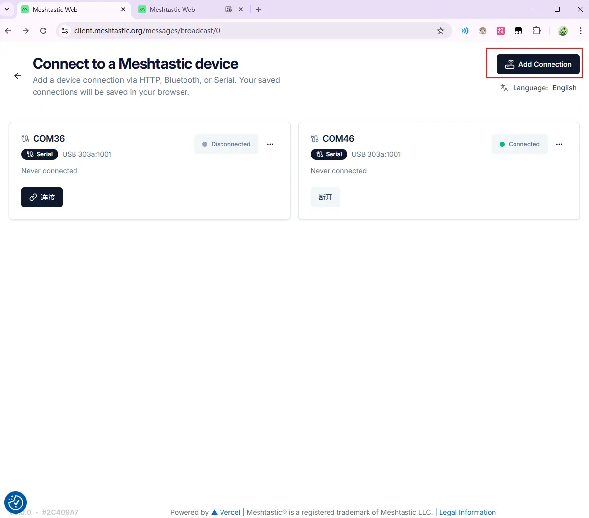
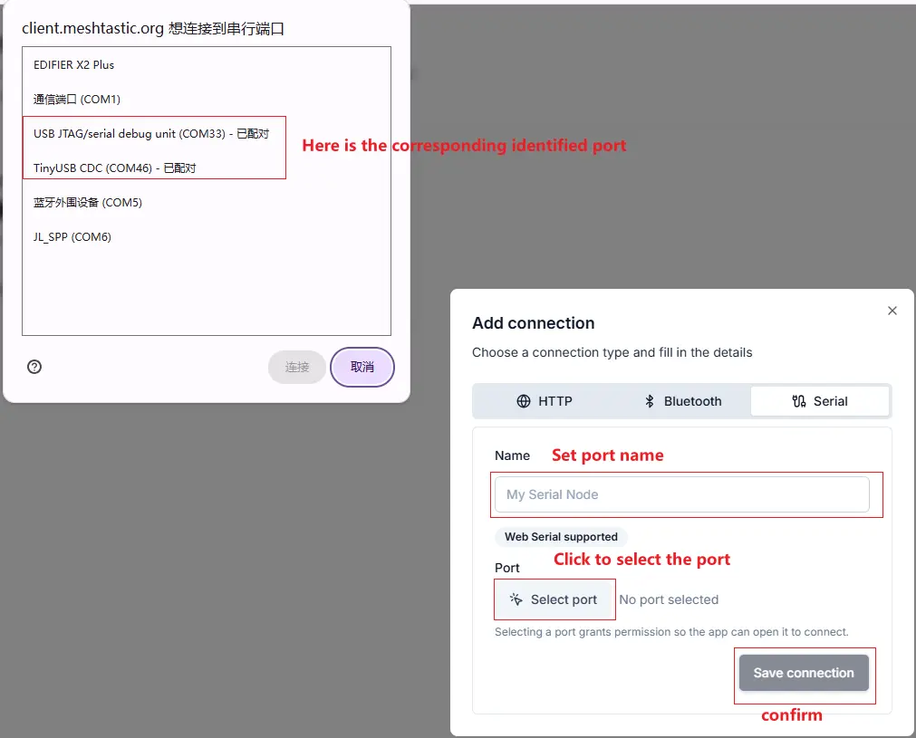
- Connect Device: Visit client.meshtastic.org.
- Configuration Interface:
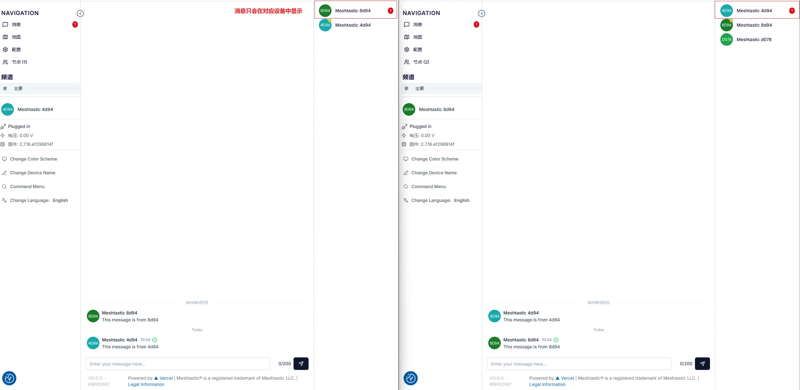
Demonstrating how to send a public message
Step 1: Do not select any device in the right sidebar, directly check the "# Primary" public channel
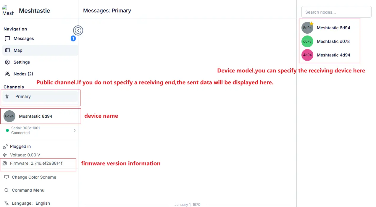
Step 2: Send the message as usual

Demonstrating how to send a message to a specific target
Step 1: Select the target device
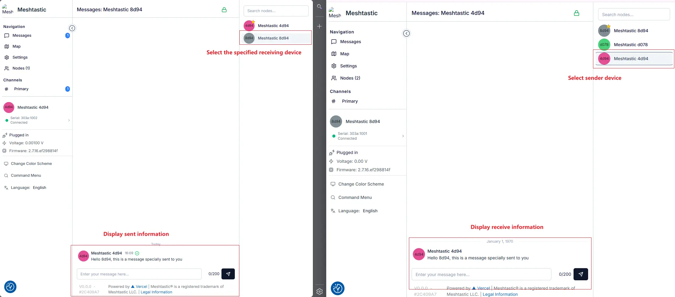
Step 2: The absence of message printouts in the public channel confirms that the message was sent directly to the target
4.2 App Interface Usage (Bluetooth)
The mobile app is the most convenient way to use the device outdoors, currently supporting Android and iOS platforms. During Bluetooth pairing, you need to connect the device to a PC and monitor the Bluetooth connection status via the serial port.
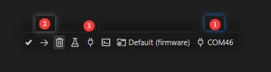
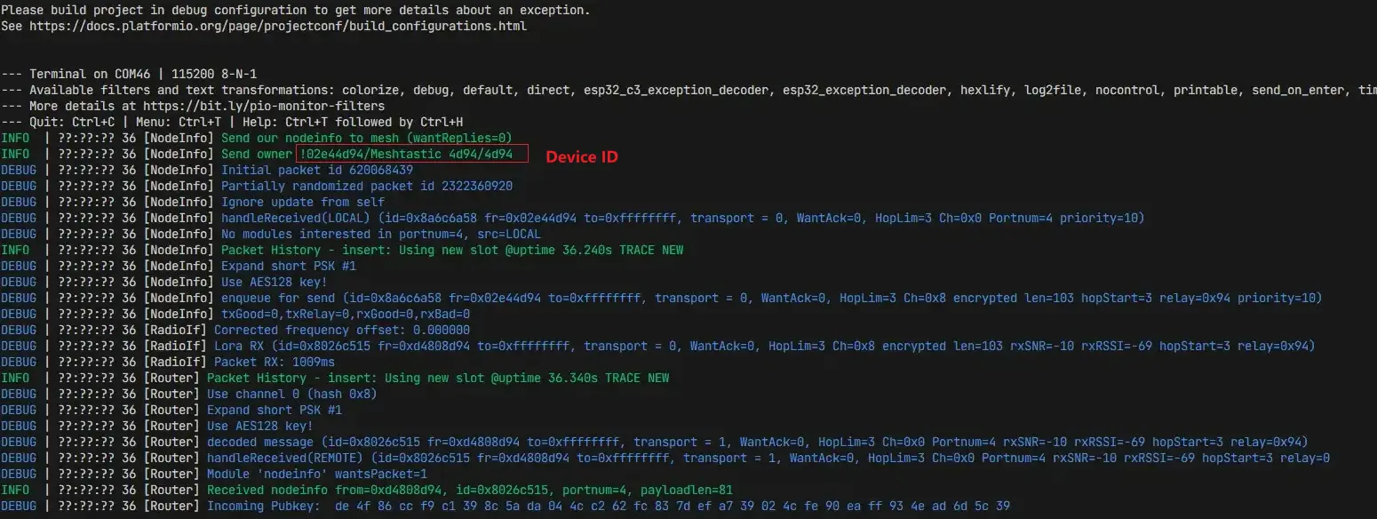
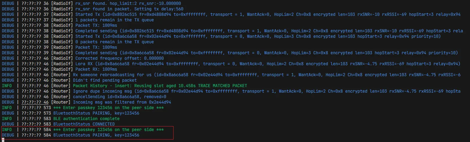
- Monitor Serial Information: View the Bluetooth connection status between the device and PC via the serial monitor.
(1). Select the corresponding serial port
(2). Compile and download (can be omitted if the firmware is already flashed)
(3). Monitor the corresponding serial port
- Bluetooth Connection: Open the app, click the "+" button to search for and pair with the device (the current app version used is 2.7.6).
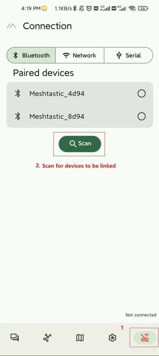
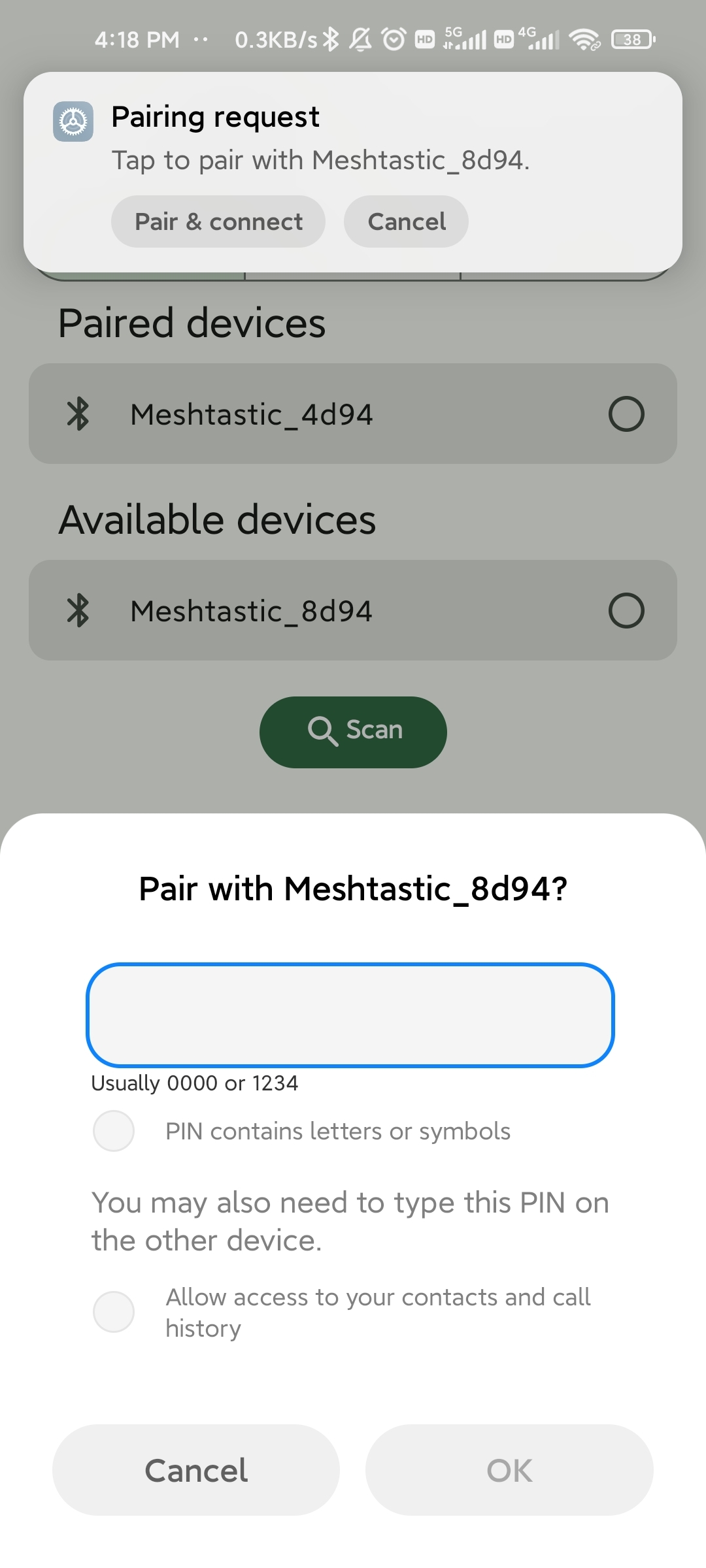
Based on the information below, the pairing password is 123456
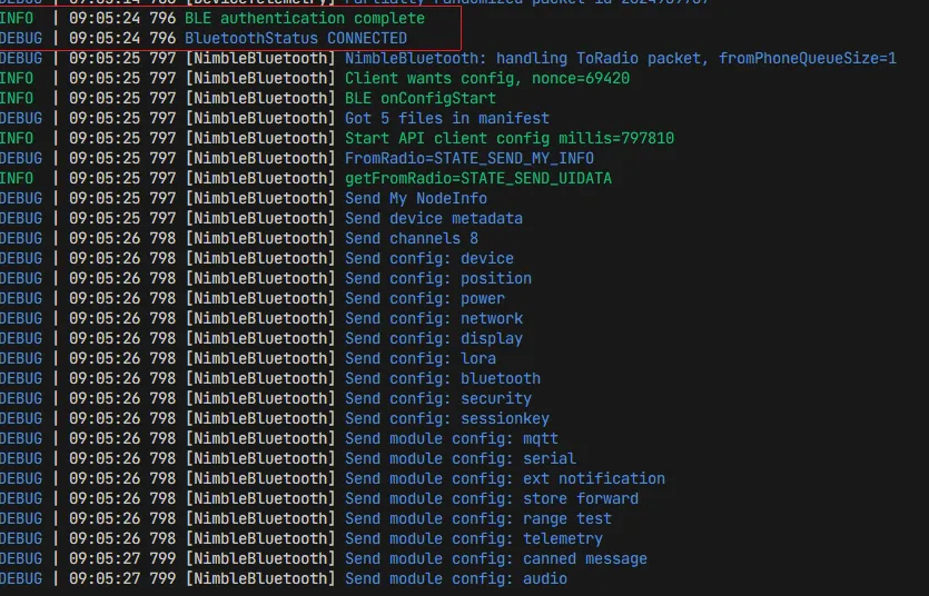
The following serial output indicates a successful Bluetooth connection
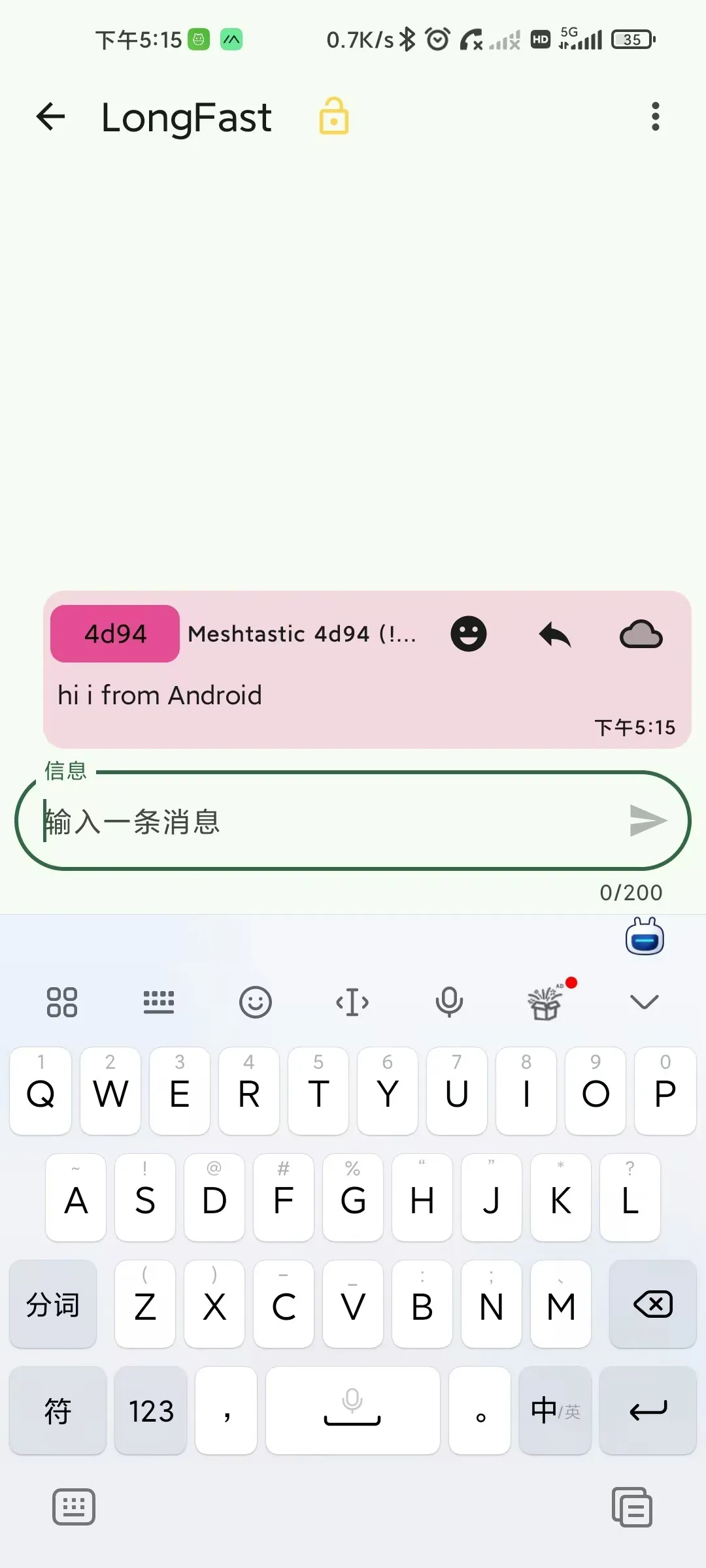
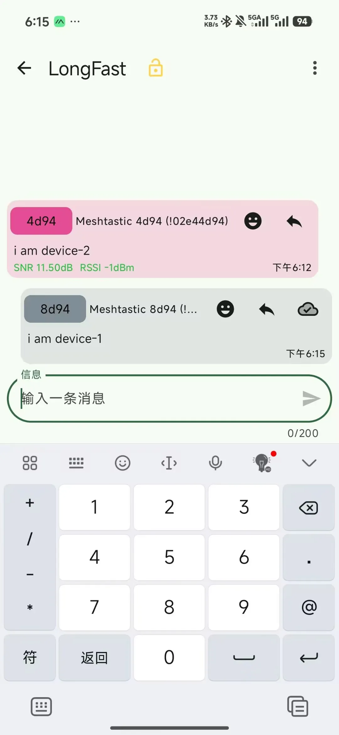
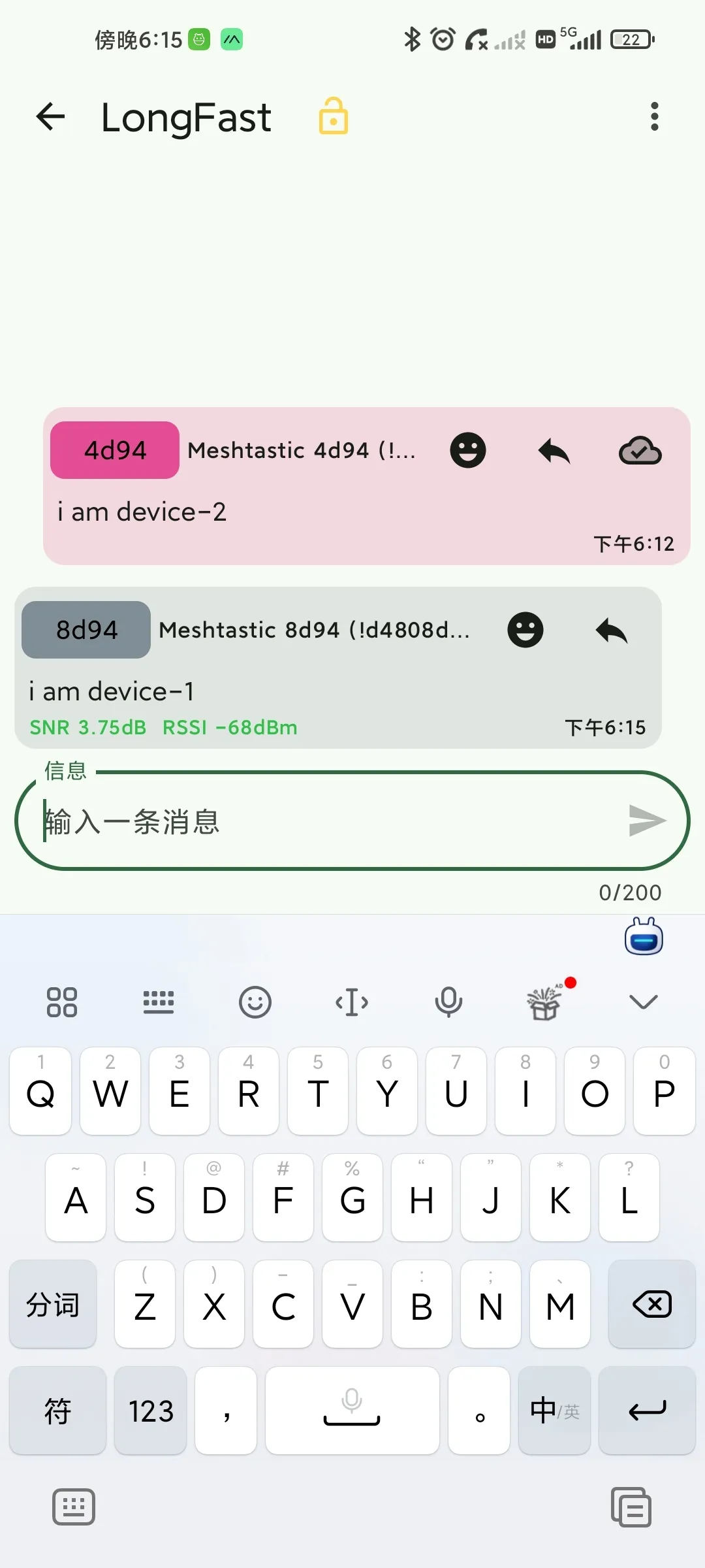
Sending a message to the device via the App
The device receives the message

After another phone connects to a different device (following the same steps), they can send messages to each other via the app
4.3 CLI Management (Advanced)
For users who need batch configuration or automated scripting, the Python CLI tool can be used.
- Environment Setup: Ensure a Python environment is installed.
- Recommended version: Python 3.8 or higher
- After installation, verify the version:
python --version
- Install Tool:
pip install meshtastic.- Upgrade command:
pip install --upgrade meshtastic
- After installation, verify the version:
meshtastic --version
A version number appearing indicates successful installation.

- Common Commands:
Enter meshtastic --port your-com --info to view information for the device on the specified port. 1 and 2 indicate viewing device info for the serial connection, 3 and 4 indicate the device IDs.
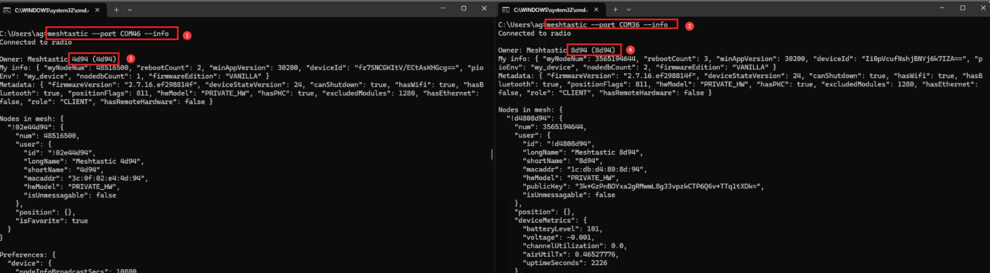
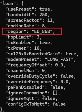
Use meshtastic --port your-com --set lora.region EU_868 to unify the operating frequency for both parties (please pay attention to the frequency range permitted by local regulations).

Re-check the device info using the meshtastic --port your-com --info command.

The presence of the content shown below in the "lora" field indicates that the region has been successfully set.
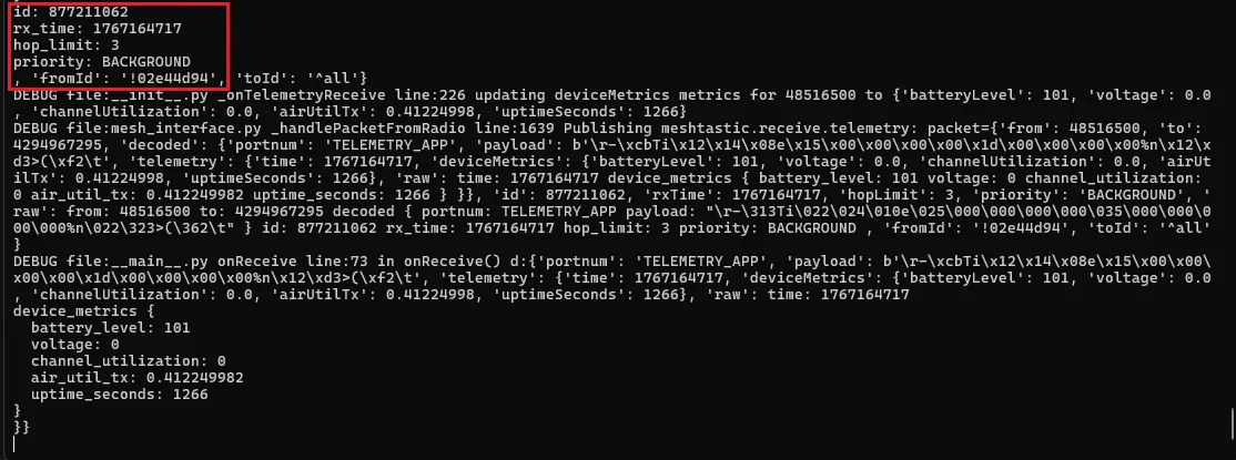
Enter meshtastic --port your-com --listen to listen on the specified port.

The appearance of the corresponding ID indicates successful listening.
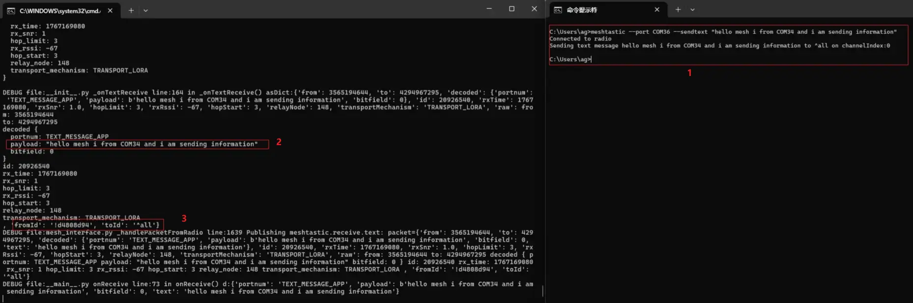
Send a message using
meshtastic --port your-com --sendtext "hello mesh i from COM34"The content in
decodecan be used to verify if the data was transmitted correctly.It shows the sender ID (fromId) and the destination ID (toId: here meaning broadcast).
Below demonstrates sending a message to a specific ID.
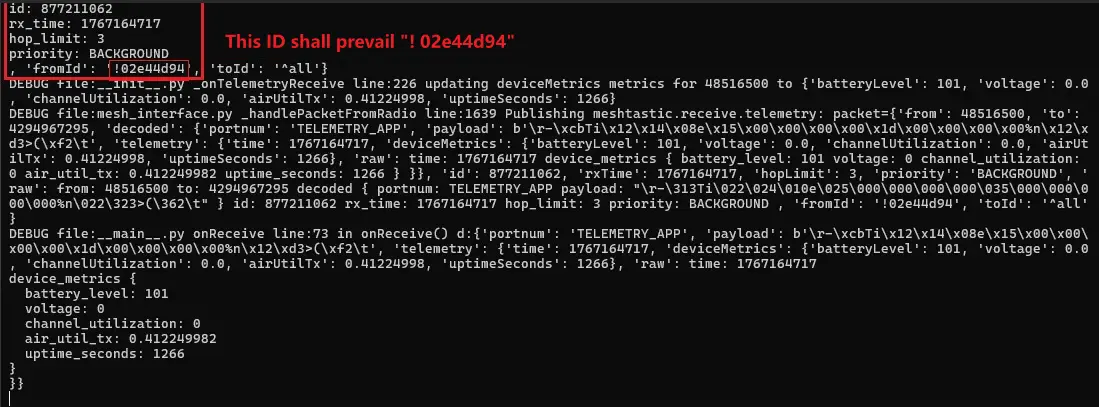
The (fromId) and (toId) fields in the listener's output indicate the sender ID and the intended recipient ID for this packet.
Send a message using meshtastic --port COM36 --dest !02e44d94 --sendtext "send info to !02e44d94”
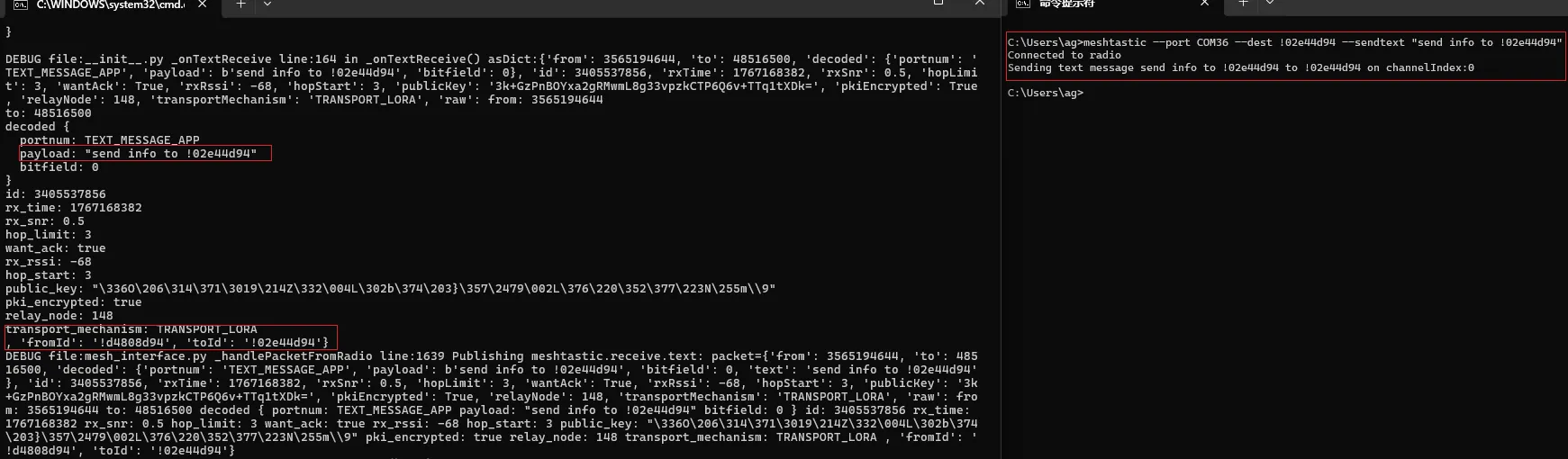
5. Key Operation Guide
5.1 Changing the Node Name
To distinguish between nodes in the network, it is recommended to change the name to an easily readable string.
- Web Interface: Modify under the
Change Device Namemenu. - App Interface: Modify in
Settings -> User.
5.2 Frequency Region Setting
Important: The correct frequency region must be set upon first use.
- China:
CN_470orCN_779 - Europe:
EU_868 - United States:
US_915
5.3 Channel Encryption and Networking
Meshtastic uses a public channel by default. If you require private communication:
- Create a new channel name.
- Enable
Encryption. - Share the generated QR Code with teammates. Scanning the code allows them to join the encrypted channel.
- Official Channel Configuration Guide: https://meshtastic.org/docs/configuration/radio/channels/
- Official QR Code/Channel URL Sharing Guide: https://meshtastic.org/docs/faq/#how-do-i-share-my-meshtastic-channel-with-other-people
5.4 MQTT Gateway / Internet Bridge
- Official Guide and Usage: https://meshtastic.org/docs/software/integrations/mqtt/
- MQTT Module Parameters: https://meshtastic.org/docs/configuration/module/mqtt/
5.5 ATAK Integration
- Official ATAK Plugin Guide: https://meshtastic.org/docs/software/integrations/integrations-atak-plugin/
- Plugin Project and Releases: https://github.com/meshtastic/ATAK-Plugin
5.6 Meshtastic Python CLI Command Details
- Official CLI Command Introduction: https://meshtastic.org/docs/software/python/cli/
6. Advanced Notes
- LR1121 Features: This chip supports multiple frequency bands (Sub-GHz, 2.4GHz). Meshtastic is continuously optimizing its support for the full frequency range of this chip.
- Low Power Optimization: For prolonged outdoor use, it is recommended to turn off unnecessary sensors or reduce the heartbeat packet frequency to extend battery life.
Firmware Flashing and Erasing
This product provides test firmware that can be flashed directly to verify whether the onboard devices are functioning properly.
- Firmware download: ESP32-S3-LR1121-XF Example. The bin file is located in the
firmwaredirectory of the example package. - Flash address:
0x00
- Firmware Flashing
- Firmware Erasing
The following uses flashing the ESP32-S3-Touch-LCD-2.8 factory firmware as an example. The same steps apply when flashing other firmware.
Download and extract Espressif's official Flash Download Tool (Download)
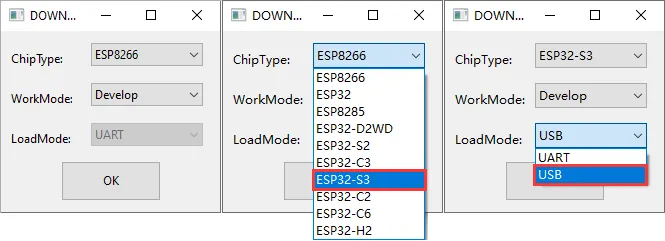
Run flash_download_tool_3.9.7.exe and select the development board's MCU and download interface, such as ESP32-S3 and USB (most devices use USB; refer to the product's hardware design for the correct interface).
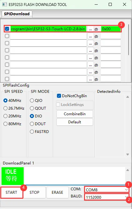
Parameter settings
- Select the COM port for the development board
- Set BAUD to the maximum value, 1152000
- Click the "..." button in the row, select the bin file provided by Waveshare, manually enter the flash address given at the top of this page in the field to its right, and select the leftmost checkbox in the row
- Click START to begin flashing
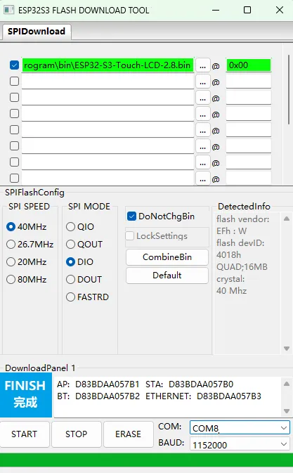
Wait for flashing to complete (this may take some time; please be patient)
Press the reset button and verify the result
Resources
1. Hardware Resources
Development Board Design Files
- Schematic: ESP32-S3-LR1121-XF.pdf
2. Technical Manuals
Official ESP32-S3 Chip Manuals
Onboard Component Datasheets
3. Example
- Demo (ESP-IDF and Arduino): ESP32-S3-LR1121-XF-Demo.zip
Support
Monday-Friday (9:30-6:30) Saturday (9:30-5:30)
Email: services01@spotpear.com
[Tutorial Navigation]
- Features
- Onboard Resources
- Specifications
- Interface Description
- Dimensions
- Working with Arduino
- Arduino Getting Started
- Setting Up Development Environment
- Example
- lr1121_cad
- lr1121_firmware_update
- lr1121_lr_fhss
- lr1121_per
- lr1121_ping_pong
- lr1121_read
- lr1121_write
- lr1121_sigfox
- lr1121_spectral_scan
- lr1121_spetrum_display
- lr1121_tx_cw
- lr1121_tx_infinite_preamble
- LoRa and LoRaWAN
- Application
- Working with ESP-IDF
- ESP-IDF Getting Started
- Setting Up Development Environment
- Example
- Example Framework
- lr1121_cad
- lr1121_firmware_update
- lr1121_lr_fhss
- lr1121_per
- lr1121_ping_pong
- lr1121_read
- lr1121_write
- lr1121_sigfox
- lr1121_spectral_scan
- lr1121_spetrum_display
- lr1121_tx_cw
- lr1121_tx_infinite_preamble
- LoRa and LoRaWAN
- Application
- Meshtastic Tutorial
- 1. Features
- 2. Hardware Preparation
- 3. Firmware Flashing
- 4. Device Management and Configuration
- 4.1 Web Interface Configuration (Bluetooth/USB/HTTP)
- 4.2 App Interface Usage (Bluetooth)
- 4.3 CLI Management (Advanced)
- 5. Key Operation Guide
- 5.1 Changing the Node Name
- 5.2 Frequency Region Setting
- 5.3 Channel Encryption and Networking
- 5.4 MQTT Gateway / Internet Bridge
- 5.5 ATAK Integration
- 5.6 Meshtastic Python CLI Command Details
- 6. Advanced Notes
- Firmware Flashing and Erasing
- Resources
- Support