- sales/support
Google Chat:---
- sales
+86-0755-88291180
- sales01
sales@spotpear.com
- sales02
dragon_manager@163.com
- support
tech-support@spotpear.com
- CEO-Complaints
zhoujie@spotpear.com
- Only Tech-Support
WhatsApp:13246739196
- Purchase/Shipping/Refund
WhatsApp:13424403025
- HOME
- >
- ARTICLES
- >
- Common Moudle
- >
- Sensors
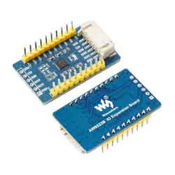
Raspberry Pi AW9523B IO Expansion Board User Guide
Overview
AW9523B use I2C interface, allows using 4 expansion boards at the same time by modifying the i2c addrtess, expand up to 64 I/O ports.
Specification
| Controller | AW9523B |
| Operating voltage | 3.3V/5V |
| IOs | 16 |
| Interface | I2C |
Interfaces
| PIN | FUNTION |
| VCC | Power input(3.3V/5V) |
| GND | GND |
| SDA | I2C Data input |
| SCL | I2C Clock input |
| INT | Intrrupt output |
| RST | Reset |
RPI User Guides
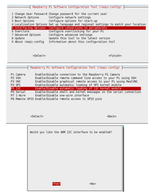
Enable I2C Interface
Open a terminal and run the following commands:
sudo raspi-config
Choose Interfacing Options -> I2C ->yes
Reboot Raspberry Pi:
sudo reboot
Install Libraries
- Install BCM2835 libraries
wget http://www.airspayce.com/mikem/bcm2835/bcm2835-1.64.tar.gz
tar zxvf bcm2835-1.60.tar.gz
cd bcm2835-1.64/
sudo ./configure
sudo make
sudo make check
sudo make install
#For more details, please refer to http://www.airspayce.com/mikem/bcm2835/
- Install WiringPi libraries
sudo apt-get install wiringpi

#For Pi 4, you need to update it:
cd /tmp
wget https://project-downloads.drogon.net/wiringpi-latest.deb
sudo dpkg -i wiringpi-latest.deb
gpio -v
#You will get 2.52 information if you install it correctly
Download Examples
Open Raspberry Pi termianl and run the following commands to download the examples:
sudo apt-get install p7zip-full -y
sudo wget  https://www.waveshare.com/w/upload/b/b8/AW9523B-IO-Expansion-Board-Code.7z
7z x AW9523B-IO-Expansion-Board-Code.7z -O./AW9523B-IO-Expansion-Board-Code
cd AW9523B-IO-Expansion-Board-Code/RaspberryPi/
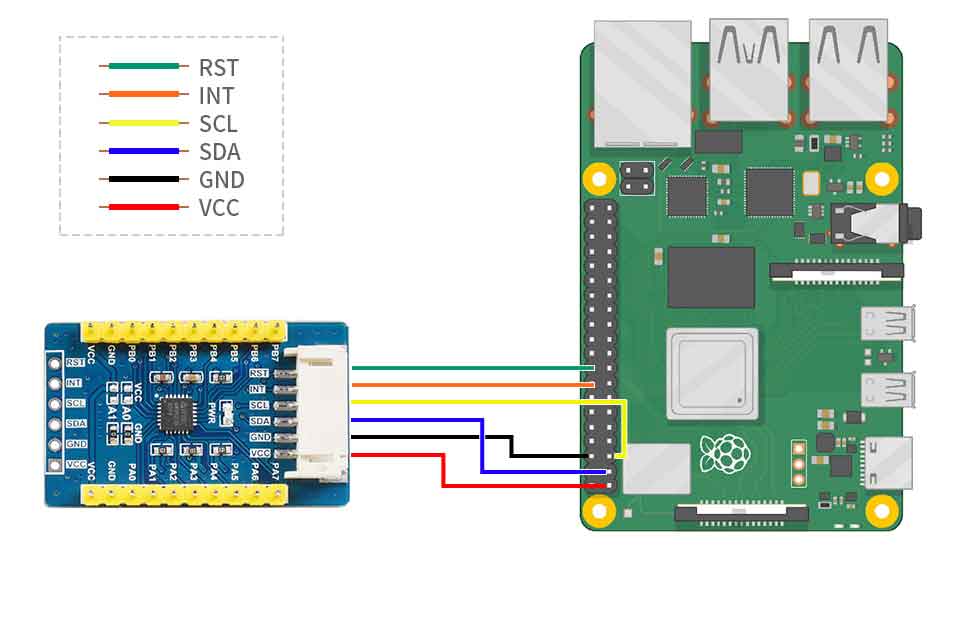
Hardware connection
| PCF8574 | Raspberry Pi | Function |
| Board order | ||
| VCC | 5V | Power input |
| GND | GND | GND |
| SDA | 3 | I2C Data input |
| SCL | 5 | I2C clock input |
| INT | 16 | Interrupt input (could NC) |
| RST | 18 | Reset module (could NC) |
Test the example
Please first negative to 'AW9523B-IO-Expansion-Board-Code/RaspberryPi/' directly by cd command before you run the codes;;
C codes
- Compile the codes and run it
cd C
sudo make clean
sudo make
sudo ./main
The examples use interrupt by default, if you want to disable the interrupt function, please add the following lines to /boot/config.txt, it will set the gpio23 to pull-up mode.
gpio=23=pu
python
Run the following commands:
cd python
sudo python AW9523B.py
Expected result
Connect the PAx pin to PBx pin, for example, connect PA0 to PB0 by cables. The PAx pins are set as output, and PBx are set as input. The status of PAx pins output toggle every 550ms in order like water lamp, every time the PAx pins toggle, it all cause the PBx pin to interrupt and printed the status to the terminal.
Arduino User Guides
The provided examples and hardware connections are based on Arduino UNO R3. For other Arduino boards, you may need to modify the connection or codes
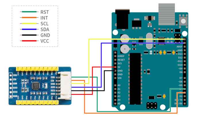
Hardware Connection
You can connect the board according to the table
| PCF8574 | Arduino | Function |
| VCC | 5V | Power input |
| GND | GND | GND |
| SDA | SDA | I2C data input |
| SCL | SCL | I2C clock input |
| INT | D3 | interrupt output |
| RST | D4 | reset |
Install Arduino IDE(Windows)
arduino IDE Installation Guides
Run the Codes
Download the examples from Demo codes, unzip the archive, and enter the AW9523B-IO-Expansion-Board-Code directory. Copy the AW9523B-Arduino-Library folder to the libraries directory which is under the installation path, generally, the path is C:\Program Files (x86)\Arduino\libraries
Open the Ariduino IDE software, Tools choose UNO, then open the examples from File-> Example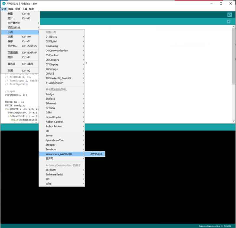
Build and upload the eamples, then open the serial monitor to check the logs
Expected
Connect the PAx pin to PBx pin, for example, connect PA0 to PB0 by cables. The PAx pins are set as output, and PBx are set as input. The status of PAx pins output toggle every 550ms in order like water lamp, every time the PAx pins toggle, it all causes the PBx pin to interrupt and printed the status to the serial monitor.
STM32 User Guides
The example and related hardware connection are based on STM32F103RBT6. If you want to use other STM32 board, you may need to change the hardare connection and codes.
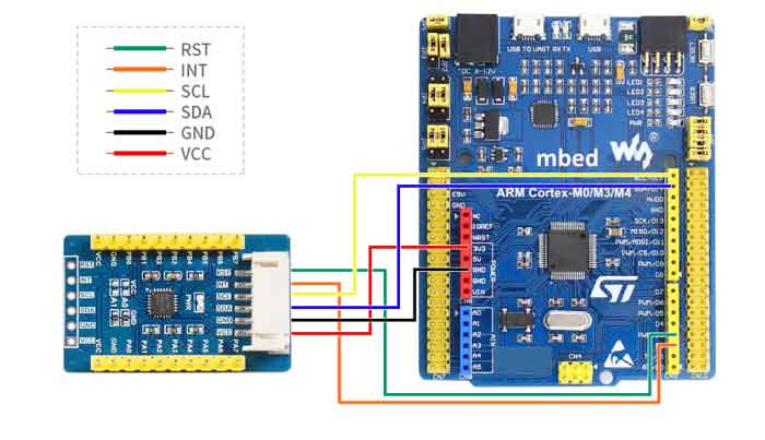
Hardware Connection
| PCF8574 | STM32 | Function |
| VCC | 3.3V | Power input |
| GND | GND | GND |
| SDA | PB9 | I2C data input |
| SCL | PB8 | I2C clock input |
| INT | PB8 | Interrupt |
| RST | PB8 | Reset |
Run the codes
The examples is based on HAL libraries. Download the Demo codes,find the STM32 directory. Open the PCF8574 IO Expansion Board.uvprojx file from STM32\STM32F103RB\MDK-ARM folder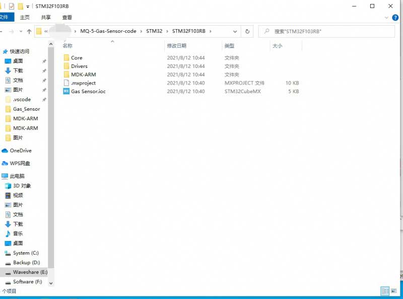
Open the main.c file, rebuild the codes and download.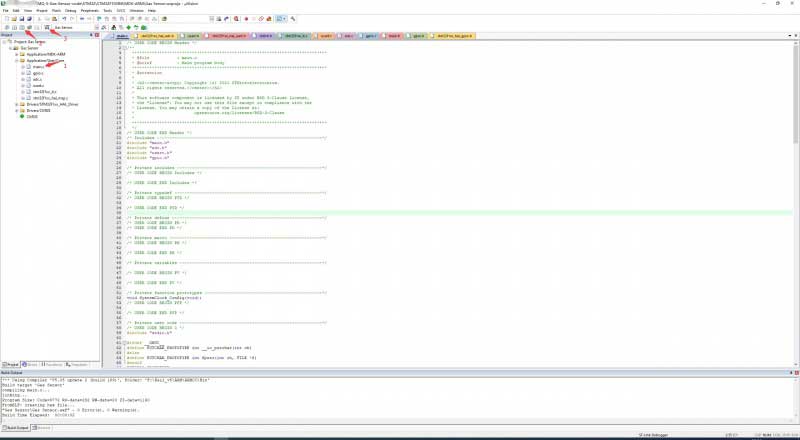
After downloading, Run the SSCOM software, choose the related COM and set the baud rate to 115200, check the logs.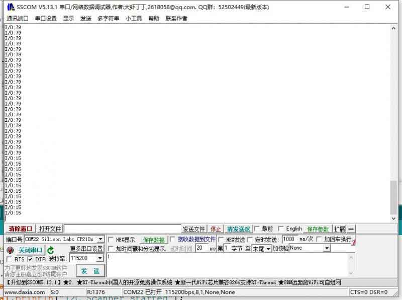
Exptect result
1、Use a multimeter to measure the voltage of every IOs, the P0~P3 are High and P4 ~ P7 are Low.
2、Open the SSCOM software, the statgus of IOs are printed on the software.