- sales/support
Google Chat:---
- sales
+86-0755-88291180
- sales01
sales@spotpear.com
- sales02
dragon_manager@163.com
- support
tech-support@spotpear.com
- CEO-Complaints
zhoujie@spotpear.com
- Only Tech-Support
WhatsApp:13246739196
- Purchase/Shipping/Refund
WhatsApp:13424403025
Raspberry Pi Pico-ePaper-2.13-B User Guide
Overview
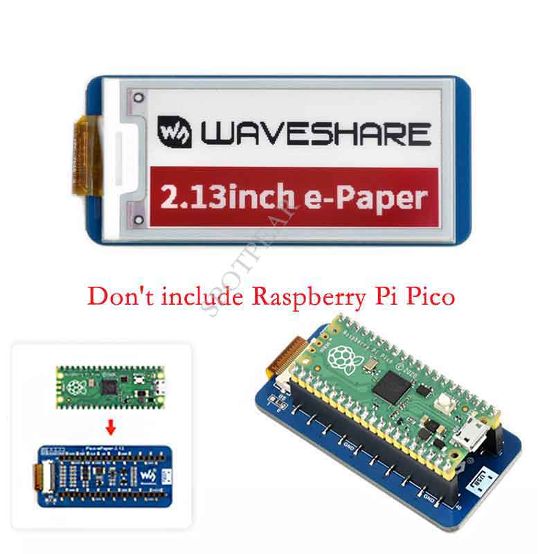
2.13inch E-Paper E-Ink Display Module For Raspberry Pi Pico, 212×104 Pixels, Black / White / Red, SPI Interface
Features
- No backlight keeps displaying last content for a long time even when power down
- Ultra-low power consumption, basically power is only required for refreshing
- SPI interface requires minimal IO pins
Specification
- Operating voltage: 3.3V/5V
- Interface:3-wire SPI, 4-wire SPI
- Outline dimensions: 65.00 × 30.50mm
- Display size:48.55 × 23.71mm
- Dot pitch: 0.229 × 0.229mm
- Resolution: 212×104 pixels
- Display color: Black, White,Red
- Greyscale: 2
- full refresh time: 15s
- Refresh power: 26.4mW(typ.)
- Standby current: <0.01uA(almost none)
- Viewing Angle: >170°
SPI Timing
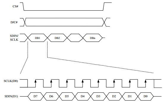
Note: Different from the traditional SPI protocol, the data line from the slave to the master is hidden since the device only has a display requirement.
- CS is slave chip select, when CS is low, the chip is enabled.
- DC is data/command control pin, when DC = 0, write command, when DC = 1, write data.
- SCLK is the SPI communication clock.
- SDIN is the data line from the master to the slave in SPI communication.
SPI communication has data transfer timing, which is combined by CPHA and CPOL.
- CPOL determines the level of the serial synchronous clock at an idle state. When CPOL = 0, the level is Low. However, CPOL has little effect on transmission.
- CPHA determines whether data is collected at the first clock edge or at the second clock edge of the serial synchronous clock; when CPHL = 0, data is collected at the first clock edge.
- There are 4 SPI communication modes. SPI0 is commonly used, in which CPHL = 0, CPOL = 0.
As you can see from the figure above, data transmission starts at the first falling edge of SCLK, and 8 bits of data are transferred in one clock cycle. Here, SPI0 is in used, and data is transferred by bits, MSB first.
Working Protocol
This product is an E-paper device adopting the image display technology of Microencapsulated Electrophoretic Display, MED. The initial approach is to create tiny spheres, in which the charged color pigments are suspending in the transparent oil and would move depending on the electronic charge. The E-paper screen displays patterns by reflecting the ambient light, so it has no background light requirement. (Note that the e-Paper cannot support updating directly under sunlight).
How to define pixels
In a monochrome picture we define the pixels, 0 is black and 1 is white.
White:□,Bit 1
Black:■:Bit 0
- The dot in the figure is called a pixel. As we know, 1 and 0 are used to define the color, therefore we can use one bit to define the color of one pixel, and 1 byte = 8pixels
- For example, If we set the first 8 pixels to black and the last 8 pixels to white, we show it by codes, they will be 16 bit as below:

For computer, the data is saved in MSB format:
So we can use two bytes for 16 pixels.
For 2.13inch e-paper B, the display colors are red, black, and white. We need to split the picture into 2 pictures, one is the black and white picture, another is the red and white picture. When transmitting, because one register controls a black or white pixel, one controls Red or white display. The black and white part of 2.13 use 1 byte to control 8 pixels, and the red and white part use 1 byte to control 8 pixels.
For example, suppose there are 8 pixels, the first 4 are red, and the back 4 are black:
They need to be disassembled into a black and white picture and a red and white picture. Both pictures have 8 pixels, but the first four pixels of the black and white picture are white, the last 4 pixels are black, and the first 4 pixels of the red and white picture One pixel is red, and the last four pixels are white.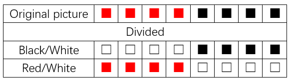
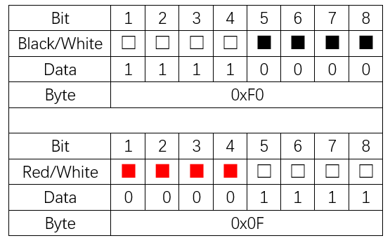
If you define that the data of white pixel is 1 and the black is 0, then we can get: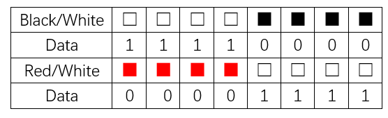
So that we can use 1 byte to control every eight pixels.