- sales/support
Google Chat: zj734465502@gmail.com
- sales
+86-0755-88291180
- sales01
sales01@spotpear.com
- sales02
dragon_manager@163.com
- support
services01@spotpear.com
- CEO-Complaints
manager01@spotpear.com
- sales/support
WhatsApp:13246739196
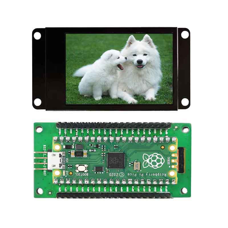
Raspberry Pi Pico 2.19inch UART LCD User Guide
一. Connection
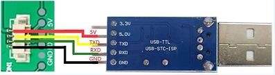
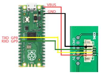
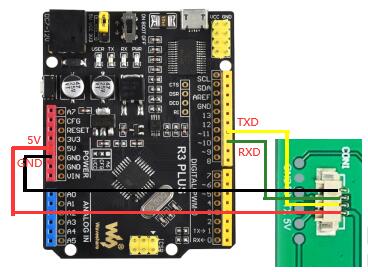
1.1 Connect to the computer through the USB to serial port module
PICO Version:
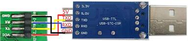
Generic version:
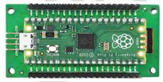
1.2 Connect with pico
The pico version inserts directly:
Generic version:
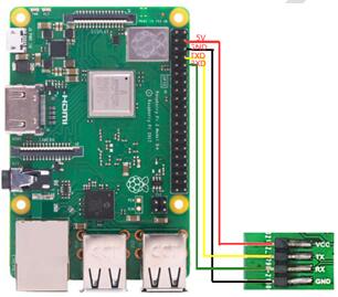
1.3 Connect with Raspberry Pi 4B
PICO Version:
Generic version:
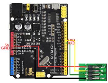
1.4 arduino
PICO Version:
Generic version:
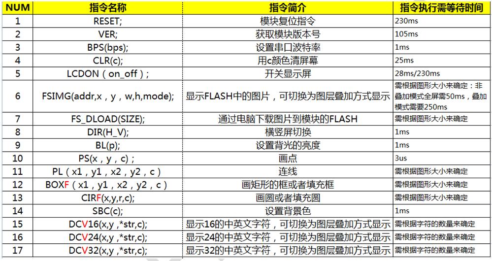
2. software instruction set
instruction | instruction code | Remark |
Module software reset command | RESET; | |
| ||
Get module version information command | VER; | |
| ||
set baud rate command | BPS(bps); | After the system is powered on, the default baud rate is 115200. |
BPS is the instruction code, and the baud rate is the value in parentheses. If you want to set the baud rate to 9600, then BPS(9600); | ||
Clear screen command | CLR(c); | Note that the range of c is 0~15. If the value of c exceeds 15, the system will not respond to this command. For the range of c values, see the color list below. |
| ||
LCD control commands | LCDON(on_off); | The parameter of On_off is only 0 or 1, and the system ignores other parameters. |
LCDON is the instruction code, and on_off means to start or close the LCD respectively. For example, LCDON(1); means to start the LCD, LCDON(0); close the LCD. | ||
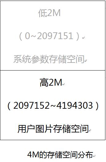
Image Display Instructions in Flash | FSIMG(addr,x,y,w,h,mode); | When Mode is 1, the white background of the picture will not be displayed. This mode is used for the overlay function of the icon and the background picture. addr is the starting address of the flash where the image is stored, it must start from 2097152 |
| ||
Image download to FLASH command | FS_DLOAD(SIZE); | The picture will be downloaded to the storage space of 2M high in FLASH, so from 2M (the position of 2097152 to store the picture), a total of 2M This command supports the burning of merged pictures, but does not support the burning of single picture files. |
FS_DLOAD is the instruction code, and SIZE is the total size of the image to be downloaded. For example, FS_DLOAD(192000); means to download a picture of 192000 bytes to flash, and the total size of the picture cannot exceed 2097152 bytes. If the value of SIZE is greater than 2097152 bytes, the system only recognizes 2097152 bytes. | ||
SDIMG is the instruction code, x, y are the starting position of the image to be displayed on the screen, w, h are the width and height of the image respectively, 'name' is the name of the file, currently only English names are supported. SDIMG(0,0,240,400,'6.bin'); means that the 6.bin file stored in the SD card is displayed at the 0,0 position of the module | ||
Horizontal and vertical screen switching | DIR(H_V); | When the system is powered on, the default is vertical screen display. |
| ||
Brightness of the backlight | BL(p); where BL is the instruction code, p is the brightness value of the backlight, and the adjustment range is: 0~255, where 0 is full bright display, and 255 is closed display. | After the system is powered on, the brightness of the backlight is 20 |
Such as BL(4); set the brightness of the backlight to 4 | ||
Dot command | PS(x, y, c); where PS is the instruction code, x, y is the starting position of the display, and c is the color of the point | This command is not suitable for large-area trace points. If there is a real need, it is recommended to build it into the module |
Such as PS(0,0,3); draw a blue point at the position of 0,0 | ||
Line drawing instructions | PL (x1, y1, x2, y2, c) where PL is the instruction code, x1, y1 are the position of the starting point, x2, y2 are the position of the end point, and c is the color of the line | Note that the range of c is 0~15. If the value of c exceeds 15, the system will ignore this operation. |
For example, PL(0,0,50,50,1); means connecting the two points from 0,0 to 50,50 with a red line | ||
Frame command | BOX (x1, y1, x2, y2, c) where BOX is the instruction code, x1, y1 is the position of the starting point, x2, y2 is the position of the end point, and c is the color of the box | Note that the range of c is 0~15. If the value of c exceeds 15, the system will ignore this operation. |
Such as BOX (0, 0, 50, 50, 1); Indicates that the starting point from 0, 0 to the end point of 50, 50, draw a red box | ||
Draw filled box command | BOXF (x1, y1, x2, y2, c); where BOXF is the instruction code, x1, y1 is the position of the starting point, x2, y2 is the position of the end point, and c is the color of the box | Ditto |
For example, BOXF (0, 0, 50, 50, 1); means starting from 0, 0 to the end point of 50, 50, and draws a red filled box | ||
Circle command | CIR(x,y,r,c); where CIR is the instruction code, x, y is the position of the center of the circle, r is the radius of the circle, and c is the color of the circle | Ditto |
Such as CIR(10, 10, 3, 0); means to draw a black circle with a radius of 3 at the center of the circle 10,10 in black | ||
Draw filled circle command | CIRF(x,y,r,c); where CIRF is the instruction code, x, y is the position of the center of the circle, r is the radius of the circle, and c is the color of the circle | Ditto |
Such as CIRF(10, 10, 3, 0); means to draw a black filled circle with a radius of 3 at the center of the circle 10, 10 in black | ||
set background color | SBC(c); where SBC is the instruction code, c is the color value of the background, and the range of c is between 0 and 63. | Ditto |
SBC(1); set the background color to red | ||
Display 16-high characters | DC16(x,y,*str,c); where DC16 is the instruction code, x, y is the starting position of the character, *str is the pointer of the character, and c is the color of the character | Ditto |
DC16(0,0,'Uart display',1); Indicates that the 'Uart display' character is displayed at the 0,0 position | ||
Display 24 characters high | DC24(x,y,*str,c); where DC24 is the instruction code, x, y is the starting position of the character, *str is the pointer of the character, and c is the color of the character | Ditto |
DC24(0,0,'Uart display',1); Indicates that the 'Uart display' character is displayed at the 0,0 position | ||
Display 32 characters high | DC32(x,y,*str,c); where DC32 is the instruction code, x, y is the starting position of the character, *str is the pointer of the character, and c is the color of the character | Ditto |
DC32(0,0,'Uart display',1); means to display the 'Uart display' character at the 0,0 position | ||
Display 16-high characters with background color | DCV16(x,y,*str,c); where DCV16 is the instruction code, x, y is the starting position of the character, *str is the pointer of the character, c is the color of the character | The setting of the background color is determined by the SBC command |
DCV16(0,0,'Uart display',1); Indicates that the 'Uart display' character is displayed at the 0,0 position | ||
Display 24-tall characters with background color | DCV24(x,y,*str,c); where DCV24 is the instruction code, x, y is the starting position of the character, *str is the pointer of the character, and c is the color of the character | The setting of the background color is determined by the SBC command |
DCV24(0,0,'Uart display',1); Indicates that the 'Uart display' character is displayed at the 0,0 position | ||
Display 32-high characters with background color |
| The setting of the background color is determined by the SBC command |
DCV32(0,0,'Uart display',1); Indicates that the 'Uart display' character is displayed at the 0,0 position |
list of colors
colors | index c value |
black | 0 |
Red | 1 |
green | 2 |
blue | 3 |
yellow | 4 |
cyan-blue | 5 |
Purple | 6 |
grey | 7 |
light grey | 8 |
brown | 9 |
dark green | 10 |
Navy blue | 11 |
dark yellow | 12 |
orange | 13 |
light red | 14 |
White | 15 |
(4) Summary of waiting time for instructions
(5) Matters needing attention when issuing instructions:
① The number of instructions must be strictly in accordance with the contents of the above list and enclosed in parentheses.
② Each instruction must be terminated with a semicolon, and each operation must be terminated with a newline. The semicolon character is: ; The newline character is: '\r\n'
③After the system is powered on, it must be ensured that the serial port of the main control is set according to the following initialization parameters: baud rate of 115200, no check bit, 1 stop bit.
3.Programming example:
1. Master (STM32F103RBT6) serial port initialization:
void uart_init(u32 bound){
// GPIO_InitTypeDef GPIO_InitStructure;
USART_InitTypeDef USART_InitStructure;
NVIC_InitTypeDef NVIC_InitStructure;
RCC_APB2PeriphClockCmd(RCC_APB2Periph_USART1|RCC_APB2Periph_GPIOA|RCC_APB2Periph_AFIO, ENABLE);//USART1_TX PA.9
GPIO_InitStructure.GPIO_Pin = GPIO_Pin_9;
GPIO_InitStructure.GPIO_Speed = GPIO_Speed_50MHz;
GPIO_InitStructure.GPIO_Mode = GPIO_Mode_AF_PP;
GPIO_Init(GPIOA, &GPIO_InitStructure);
//USART1_RX PA.10
GPIO_InitStructure.GPIO_Pin = GPIO_Pin_10;
GPIO_InitStructure.GPIO_Mode = GPIO_Mode_IN_FLOATING;
GPIO_Init(GPIOA, &GPIO_InitStructure);
//Usart1 NVIC ÅäÖÃ
NVIC_InitStructure.NVIC_IRQChannel = USART1_IRQn;
NVIC_InitStructure.NVIC_IRQChannelPreemptionPriority=3 ;
NVIC_InitStructure.NVIC_IRQChannelSubPriority = 3; //
NVIC_InitStructure.NVIC_IRQChannelCmd = ENABLE;
NVIC_Init(&NVIC_InitStructure);
USART_InitStructure.USART_BaudRate = bound;//Ò»°ãÉèÖÃΪ9600;
USART_InitStructure.USART_WordLength = USART_WordLength_8b;
USART_InitStructure.USART_StopBits = USART_StopBits_1;
USART_InitStructure.USART_Parity = USART_Parity_No;
USART_InitStructure.USART_HardwareFlowControl = USART_HardwareFlowControl_None;
USART_InitStructure.USART_Mode = USART_Mode_Rx | USART_Mode_Tx;
USART_Init(USART1, &USART_InitStructure);
USART_ITConfig(USART1, USART_IT_RXNE, ENABLE);//
USART_Cmd(USART1, ENABLE);
}
void UartSend(char * databuf) //Serial port sending function
{
u8 i=0;
while (1)
{
{
USART_SendData(USART1, databuf[i]); //
while(USART_GetFlagStatus(USART1, USART_FLAG_TXE) == RESET){}; //
i++;
}
else return;
}
}
int main(void)
{
SystemInit();//Initialize RCC and set the main frequency of the system to 72MHZ
delay_init(72); //Delayed initialization
uart_init(115200); //The serial port is initialized to 115200
delay_ms(500);
for(;;)
{
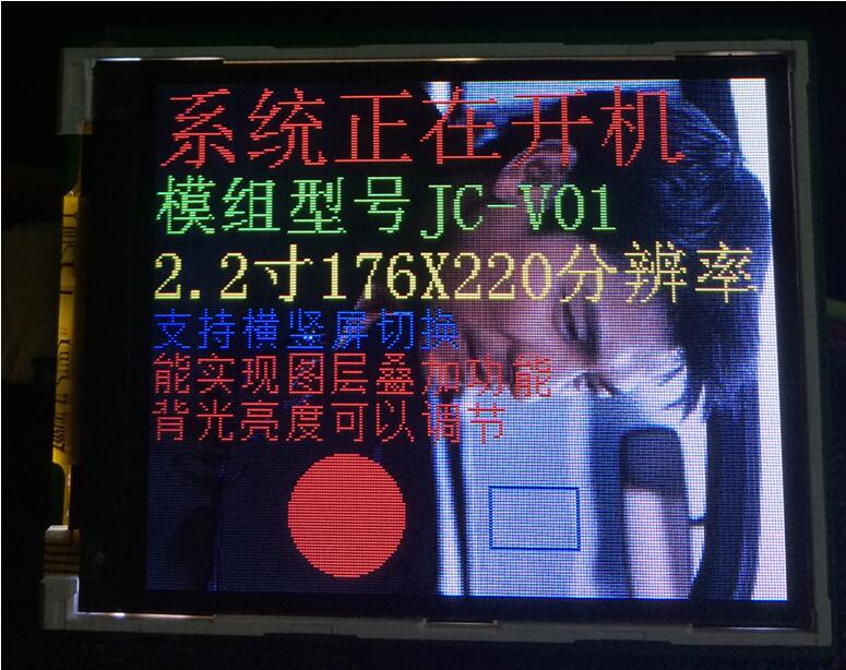
UartSend("SBC(15);DIR(0);FSIMG(2329472,0,0,176,220,0);DIR(1);SBC(10);\r\n");
CheckBusy();
UartSend("DC32(0,0,'system is booting ',1);\r\n");
CheckBusy();
UartSend("DC24(0,32,'Module model JC -V01',2);\r\n");
CheckBusy();
UartSend("DC24(0,56,'2.2寸176X220Resolution',4);\r\n");
CheckBusy();
UartSend("DC16(0,80,'Support horizontal and vertical screen switching ',3);\r\n");
CheckBusy();
UartSend("DC16(0,96,'Can realize layer overlay function',1);\r\n");
CheckBusy();
UartSend("DC16(0,112,'Backlight brightness can be adjuste',1);\r\n");
CheckBusy();
UartSend("PS(10,10,14);\r\n");
CheckBusy();
UartSend("BOX(120,140,150,160,3);\r\n");
CheckBusy();
CheckBusy();
while(1);
}
}
The effect of the function execution:
Please contact our salesperson for the complete STM32 test project.
Programming skills:
① If the real-time requirements of the system are very high, there is no need to wait between commands. The main control can determine whether the command has been executed through the three characters of OK\r\n returned by the detection module. Improve the real-time performance of the program. For details, please refer to the complete test code.
②The module allows the serial port to send up to 24 commands at one time, which can greatly improve the efficiency of programming, but it must be noted that the end of the command must be \r\n as the terminator, and the waiting time after sending is the waiting time for the last command time.
2. Pico(Python)
Note: The resolution of the following example is 376x240 (the red font below needs to be modified according to the actual resolution and image address, and the blue font should be careful not to exceed the actual range) The code can be downloaded from the website according to the serial port screen
from machine import UART, Pin
import time
import sys
uart1 = UART(1, baudrate=115200, bits=8, parity=None, stop=1,tx=Pin(8), rx=Pin(9))
uart0 = UART(0, baudrate=115200, bits=8, parity=None, stop=1,tx=Pin(0), rx=Pin(1))
txData = u'CLR(0);\r\n'
uart1.write(txData)
time.sleep(0.1)
txData = b"DIR(1);DC24(20,0,\'spotpear\',1);DC24(20,70,\' UART LCD for Pico\',2);BOX(120,140,160,180,3);CIRF(70,150,30,4);DELAYMS (500000);DELAYMS (500000);CLR(0);DIR(1);DELAYMS(400);CLR(6);DELAYMS (400);FSIMG(2097152,0,0,376,240,0);DELAYMS(600);CLR(4);DELAYMS(400);FSIMG(2277632,0,0,376,240,0);;DELAYMS(600);CLR(5);DELAYMS(400);FSIMG(2458112,0,0,376,240,0);\r\n"
uart1.write(txData.decode('unicode'))
time.sleep(0.1)
rxData = bytes()
while uart0.any() > 0:
rxData += uart0.read(1)
print(rxData.decode('utf-8'))
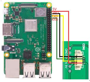
3. Raspberry Pi 3
Note: The resolution of the following example is 220 x 176 (the red font below needs to be modified according to the actual resolution and image address, and the blue font should be careful not to exceed the actual range) Raspberry Pi 2/3 code can be downloaded from the website
#include <stdio.h>
#include <wiringPi.h>
#include <wiringSerial.h>
int main()
{
int fd;
if(wiringPiSetup() < 0)return 1;
// if((fd = serialOpen("/dev/ttyAMA0",115200)) < 0)return 1;
if((fd = serialOpen("/dev/ttyS0",115200)) < 0)return 1;
printf("serial test start ...\n");
delay(800);
serialPrintf(fd,"RESET;\r\n");//reset the LCD
delay(100);
serialPrintf(fd,"BPS(115200);\r\n");//Set Baud rate
delay(100);
serialPrintf(fd,"CLR(0);\r\n");//Clean LCD with black color
delay(100);
serialPrintf(fd,"CLR(1);\r\n");//Clean LCD with red color
delay(100);
serialPrintf(fd,"CLR(15);\r\n");//Clean LCD with white color
delay(100);
serialPrintf(fd,"DIR(0);\r\n");//Vertical display
delay(100);
serialPrintf(fd,"DCV24(0,0,spotpear,0);\r\n");
//display "spotpear" at coordinate(0.0),Font color :0-black;background color :default black
delay(100);
serialPrintf(fd,"SBC(1);\r\n");//set background color red
delay(100);
serialPrintf(fd,"DCV24(0,24,spotpear,0);\r\n");
//display "spotpear" at coordinate(X-0.Y-24)
delay(500);
serialPrintf(fd,"DCV24(0,24,spotpear,3);\r\n");//,Font color :3-;
delay(500);
serialPrintf(fd,"CLR(0);\r\n");//Clean LCD with black color
delay(500);
serialPrintf(fd,"DIR(1);\r\n");//Horizontal display
delay(500);
serialPrintf(fd,"DCV16(0,24,spotpear,0);\r\n");
delay(500);
serialPrintf(fd,"DCV32(0,0,spotpear,0);\r\n");
delay(500);
serialPrintf(fd,"CIRF(40,80,20,3);\r\n");//filling circle coordinate(X-40.Y-80,r-20,color-3)
delay(100);
serialPrintf(fd,"CIR(70,150,20,1);\r\n");//circle coordinate(X-70.Y-150,r-20,color-1)
delay(500);
serialPrintf(fd,"BOXF(70,150,90,170,3);\r\n");//rectangle coordinate
delay(500);
serialPrintf(fd,"BOX(40,80,70,110,3);\r\n");//rectangle coordinate
delay(500);
serialPrintf(fd,"PL(0,0,220,176,6);\r\n");//line: color-6,
delay(500);
serialPrintf(fd,"PS(110,110,4);\r\n");//line: color-6,
delay(1000);
serialPrintf(fd,"DIR(0);\r\n");//Vertical display
delay(100);
serialPrintf(fd,"FSIMG(2097152,0,0,176,220,0);\r\n");
//load picture-1 from LCD(picture loaded by computer UART software in advance)
delay(500);
serialPrintf(fd,"FSIMG(2174592,0,0,176,220,0);\r\n");//load picture-2 from LCD
delay(500);
serialPrintf(fd,"FSIMG(2252032,0,0,176,220,0);\r\n");
delay(500);
serialPrintf(fd,"BL(1023);\r\n");////Backlight ightness:1024-open display
delay(1000);
serialPrintf(fd,"BL(0);\r\n");//Backlight ightness:0-stop display
delay(300);
// serialPrintf(fd,"RESET;\r\n");//reset*/
// delay(300);
serialPrintf(fd,"DCV24(0,0,spotpear,0);\r\n");
delay(300);
//while(1)
//{
// serialPutchar(fd,serialGetchar(fd));
//}
serialClose(fd);
return 0;
}
4. Arduino
Note: The resolution of the following example is 220 x 176 (the red font below needs to be modified according to the actual resolution and image address, and the blue font should be careful not to exceed the actual range) Raspberry Pi 2/3 code can be downloaded from the website
UARTLCD22-1
/*
Software serial multple serial test
Receives from the hardware serial, sends to software serial.
Receives from software serial, sends to hardware serial.
The circuit:
* RX is digital pin 10 (connect to TX of other device)
* TX is digital pin 11 (connect to RX of other device)
Note:
Not all pins on the Mega and Mega 2560 support change interrupts,
so only the following can be used for RX:
10, 11, 12, 13, 50, 51, 52, 53, 62, 63, 64, 65, 66, 67, 68, 69
Not all pins on the Leonardo support change interrupts,
so only the following can be used for RX:
8, 9, 10, 11, 14 (MISO), 15 (SCK), 16 (MOSI).
created back in the mists of time
modified 25 May 2012
by Tom Igoe
based on Mikal Hart's example
This example code is in the public domain.
*/
#include <SoftwareSerial.h>
SoftwareSerial mySerial(10, 11); // RX, TX
void setup()
{
mySerial.begin(115200);
delay(800);
mySerial.println("RESET;\r\n");
delay(100);
mySerial.println("BPS(115200);\r\n");
delay(100);
mySerial.println("CLR(1);\r\n");
delay(500);
mySerial.println("CLR(15);\r\n");
delay(500);
mySerial.println("DIR(0);\r\n");
delay(100);
mySerial.println("DCV24(0,0,spotpear,0);\r\n");
delay(100);
mySerial.println("SBC(1);\r\n");
delay(100);
mySerial.println("DCV24(0,24,spotpear,0);\r\n");
delay(300);
mySerial.println("DCV24(0,24,spotpear,3);\r\n");
delay(300);
mySerial.println("CLR(0);\r\n");
delay(300);
mySerial.println("FSIMG(2097152,0,0,176,220,0);\r\n");
delay(300);
mySerial.println("FSIMG(2174592,0,0,176,220,0);\r\n");
delay(300);
mySerial.println("FSIMG(2252032,0,0,176,220,0);\r\n");
delay(300);
mySerial.println("BL(1023);\r\n");
delay(1000);
mySerial.println("BL(0);\r\n");
delay(1000);
}
void loop() // run over and over
{
delay(300);
}
UARTLCD22-2
/*
Software serial multple serial test
Receives from the hardware serial, sends to software serial.
Receives from software serial, sends to hardware serial.
The circuit:
* RX is digital pin 10 (connect to TX of other device)
* TX is digital pin 11 (connect to RX of other device)
Note:
Not all pins on the Mega and Mega 2560 support change interrupts,
so only the following can be used for RX:
10, 11, 12, 13, 50, 51, 52, 53, 62, 63, 64, 65, 66, 67, 68, 69
Not all pins on the Leonardo support change interrupts,
so only the following can be used for RX:
8, 9, 10, 11, 14 (MISO), 15 (SCK), 16 (MOSI).
created back in the mists of time
modified 25 May 2012
by Tom Igoe
based on Mikal Hart's example
This example code is in the public domain.
*/
#include <SoftwareSerial.h>
SoftwareSerial mySerial(10, 11); // RX, TX
void setup()
{
mySerial.begin(115200);
delay(800);
mySerial.println("RESET;\r\n");
delay(300);
mySerial.println("DIR(1);\r\n");
delay(500);
mySerial.println("CLR(0);\r\n");
delay(500);
mySerial.println("DCV16(0,24,spotpear,0);\r\n");
delay(300);
mySerial.println("DCV32(0,0,spotpear,0);\r\n");
delay(300);
mySerial.println("CIRF(40,80,20,3);\r\n");
delay(300);
mySerial.println("CIR(70,150,20,1);\r\n");
delay(300);
mySerial.println("BOXF(70,150,90,170,3);\r\n");
delay(300);
mySerial.println("BOX(40,80,70,110,3);\r\n");
delay(300);
mySerial.println("PL(0,0,220,176,6);\r\n");
delay(300);
mySerial.println("PS(110,110,4);\r\n");
delay(300);
}
void loop() // run over and over
{
delay(1000);
}
5. Picture storage and reading operation instructions
(Note: The following example is a 240x400 picture, this module is 176x220, remember to adjust this parameter during actual operation)
(1) If the total size of the picture that the user needs to store is less than 2M, the picture can be stored in the 2M picture storage space opened up by the module for the user (that is, the high 2M space of FLASH).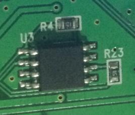
板子的FLASH芯片
(2) How to obtain the image file to be downloaded:
①Get the picture material with bmp suffix from the art design department (this BMP is in 24-bit format). If the material is a picture in other formats (such as jpeg or png), it must be saved in BMP format.
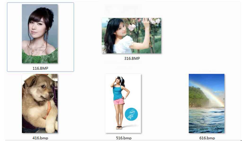
The above are all the material pictures in bmp format to be displayed
②Open Image2Lcd.exe modulo software, import the picture, note that the settings in the red box must be consistent with those in the picture, and the resolution of the blue box needs to be determined according to the specific picture size.
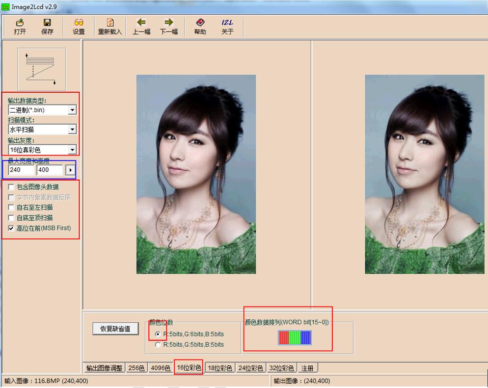
Software interface after importing pictures
③Click the save button at the top left of the software to save it as a bin file, and use the same method to save all the pictures you need as a bin file.
④Open the EzOSD.exe file, select "Merge", select the path in the upper left and double-click to select the bin file just saved from the lower right. The selected file will be displayed in the list on the right.
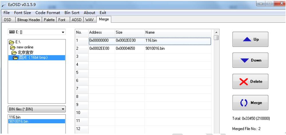
Note that I only selected 2 bin files at this time, the first one is a 240x400 full-screen image, the second one is a 90x100 window image, and the total size of the two images is: 210000 bytes
⑤ Click the Merge button at the bottom right to merge and save as Pic.bin
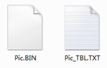
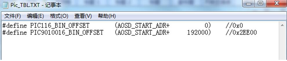
Note Pic_TBL.TXT is the picture merging information (including offset address and size), as shown below
At this point, the Pic.bin to be burned has been created.
(3) Download Pic.bin to the module (download using serial terminal)
①Open the serial port terminal SSCOM 3.3 exe, connect the module to the serial port of the computer, and set the parameters such as the baud rate of the terminal.
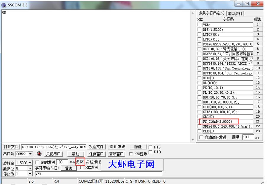
② Note that you need to select the Send new line check box. At this time, use the baud rate of 115200 to send the FS_DLOAD(210000); command to the module. After receiving the command, the module will return the information that the FLASH is erasing to the terminal, and wait for the FLASH erasing to complete.
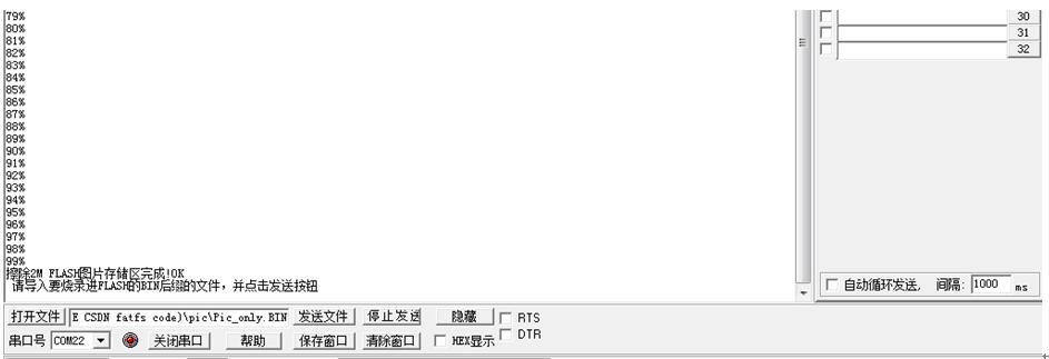
③After the erasing is completed, you can import the Pic.bin file just generated by pressing the ''Open File'' button.
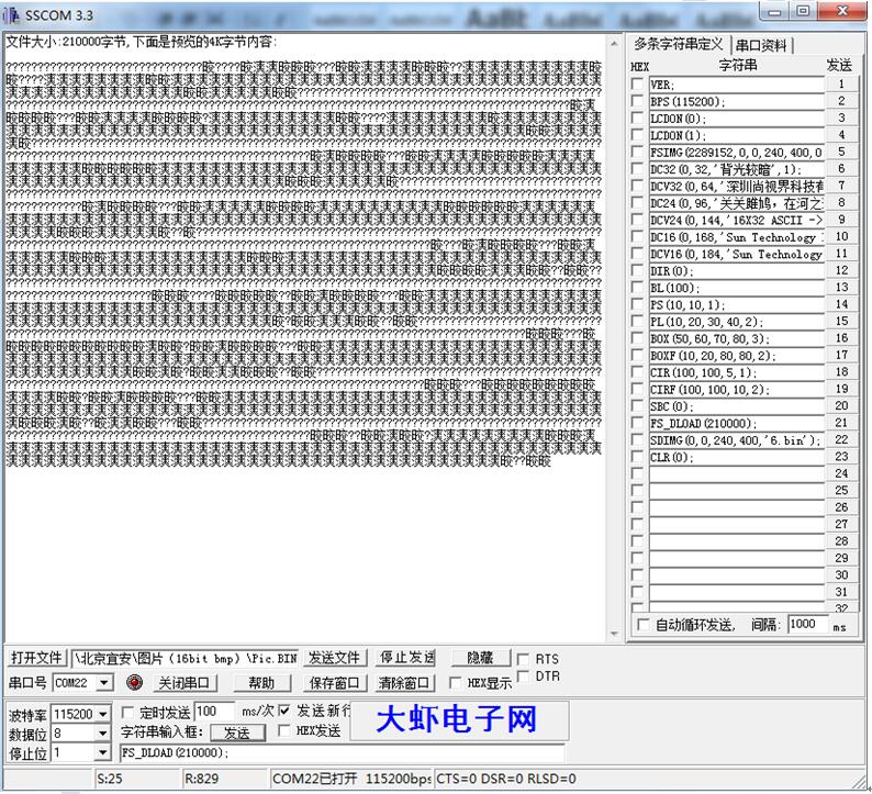
The file has been imported, click the ''Send file'' button 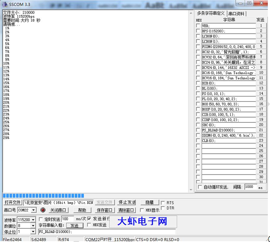
④Wait for the programming to complete.
(5) Display the pictures downloaded to FLASH
①FSIMG(2097152,0,0,240,400,0);
Start to display the first picture at 0,0 of the module, of which 2097152 is the starting address of picture storage. The size of the picture is 240*400.
②FSIMG(2097152+192000,0,0,90,100,0);
Display the second picture, where the offset address is +192000, which means that the second picture is accessed immediately after the first picture.