


- sales/support
Google Chat: zj734465502@gmail.com
- sales
+86-0755-88291180
- sales01
sales01@spotpear.com
- sales02
dragon_manager@163.com
- support
services01@spotpear.com
- CEO-Complaints
manager01@spotpear.com
- sales/support
WhatsApp:13246739196
Raspberry PiSX1262 915M LoRa HAT User Guide
Instruction
This is a Raspberry Pi LoRa HAT based on SX1262, covers 915MHz frequency band. It allows data transmission up to 5km through serial port.
Features
- Standard Raspberry Pi 40PIN GPIO extension header, supports Raspberry Pi series boards
- Onboard CP2102 USB TO UART converter, for serial debugging
- Brings the UART control interface, for connecting host boards like Arduino/STM32
- 4x LED indicators, easy to check the module status
- LoRa spread spectrum modulation technology, up to 81 available signal channel, longer communication distance, more robust to interference
- Auto multi-level repeating, suit for ultra long range communication, allows multi network on the same region
- Low power consumption features like deep sleeping and Wake on Radio, ideal for battery-powered applications
- Customizable communication key which won't be retrieved, greatly improves the security of user data
- Supports LBT, monitoring the signal channel noise before transmitting, greatly improves the success ratio under extreme environment
- Supports RSSI signal intensity indicating, for evaluating signal quality, tuning the network
- Supports wireless parameter configuration, by sending wireless command/data packet, remotely configure or retrieve the module parameter
- Supports fixed-point transmission, broadcast, signal channel monitor
- Comes with development resources and manual (examples for Raspberry Pi/STM32)
Specification
| Consumption | Transmit Current | 133mA (Transient current) |
| Receive Current | 11mA | |
| Sleep Current | 2uA (LoRa module deep sleep) | |
| MAX Transmit Power | 22.0dBm(10, 13, 17, 22dBm Selectable) | |
| Transmit Length | 240 Bytes (32, 64, 128, 240 Bytes Selectable) | |
| Buffer | 1000 Bytes | |
| Working bands | 850.125 ~ 930.125MHz | |
| Receive Sensitivity | 147dBm@0.3Kbps (On air) | |
| Interface | UART | |
| Range | 5KM(Sunny day; open area; Antenna: AUX 5dBi, Height 2.5m; Air Speed: 2.4kbps) | |
| Working voltage | 5V | |
| Logic voltage | 3.3V | |
| Working Temperature | 40 ~ 85°C | |
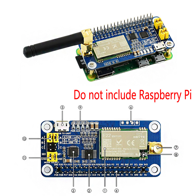
Hardware description
- SX1262 LoRa module
- 74HC125V: voltage level translator
- CP2102: USB TO UART converter
- Raspberry Pi GPIO connector: for connecting with Raspberry Pi
- USB TO UART port
- UART header: for connecting host boards like STM32/Arduino
- SMA antenna connector
- IPEX antenna connector
- Indicators:
- RXD/TXD: UART RX/TX indicator
- AUX: auxiliary indicator
- PWR: power indicator
- UART selection jumpers
- A: control the LoRa module through USB TO UART
- B: control the LoRa module through Raspberry Pi
- C: access Raspberry Pi through USB TO UART
- LoRa mode selection jumpers
- short M0, short M1: transmission mode
- short M0, open M1: configuration mode
- open M0, short M1: WOR mode
- open M0, open M1: deep sleep mode
【Note】
- Mode 0: Transmission mode, Module transmit data when users send data to UART interface. Wireless receiving is enabled to receive data and send to UART interface when idle.
- Mode 1:When it is defined to Transmit, user need to add wakeup codes before transmitting, receiving is same as Mode 0.
- Mode 2: Wireless transmit and wireless receive are disabled, users can configure configuration according to #Registers Configuration
- Mode 3: Wireless transmit and wireless receive are disabled, module enter deep sleep mode. The module will configure when switching to other modes.
- RXD/TXD: UART RX/TX indicator
- AUX: auxiliary indicator
- PWR: power indicator
- A: control the LoRa module through USB TO UART
- B: control the LoRa module through Raspberry Pi
- C: access Raspberry Pi through USB TO UART
- short M0, short M1: transmission mode
- short M0, open M1: configuration mode
- open M0, short M1: WOR mode
- open M0, open M1: deep sleep mode
Use Guides
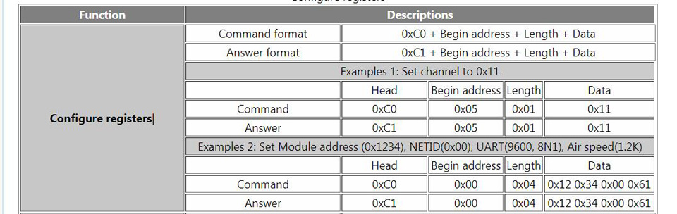
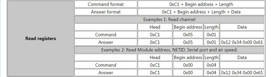
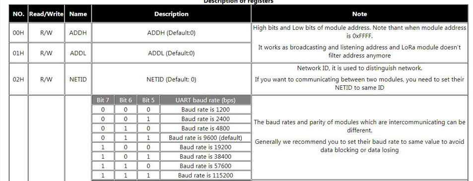
Registers Configuration
If the module is set to configuration mode (Mode 2), you can configure registers according to the table below. (Baud rate: 9600, 8N1)
Configure registers
【Note】
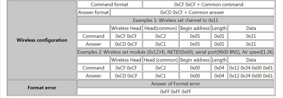
- 1. When wireless configuring, you need to firstly configure Modules address, NETID, Air speed and Key of both modules to same values. For example, if Modules A: Module address is 1, NETID is 1, Air speed is 2.4Kbps and Key is 1. Module B: Module address is 2, NETID is 2, Air speed is 62.5Kbps and Key is 2. If you want to use Module A to configure Module B via wireless network, you need to set Module A to be same as Module B. Then you can use 0xCF 0xCF command to configure Module B via wireless network.
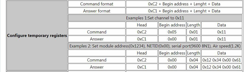
- 2. After configure temporary registers, LoRa modules work by settings of temporary registers. If LoRa modules restart, the settings of temporary are invalid, LoRa module will re-configure registers according to network settings by 0xC1 commands.
- 1. When wireless configuring, you need to firstly configure Modules address, NETID, Air speed and Key of both modules to same values. For example, if Modules A: Module address is 1, NETID is 1, Air speed is 2.4Kbps and Key is 1. Module B: Module address is 2, NETID is 2, Air speed is 62.5Kbps and Key is 2. If you want to use Module A to configure Module B via wireless network, you need to set Module A to be same as Module B. Then you can use 0xCF 0xCF command to configure Module B via wireless network.
- 2. After configure temporary registers, LoRa modules work by settings of temporary registers. If LoRa modules restart, the settings of temporary are invalid, LoRa module will re-configure registers according to network settings by 0xC1 commands.
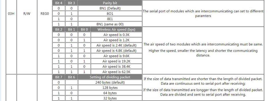
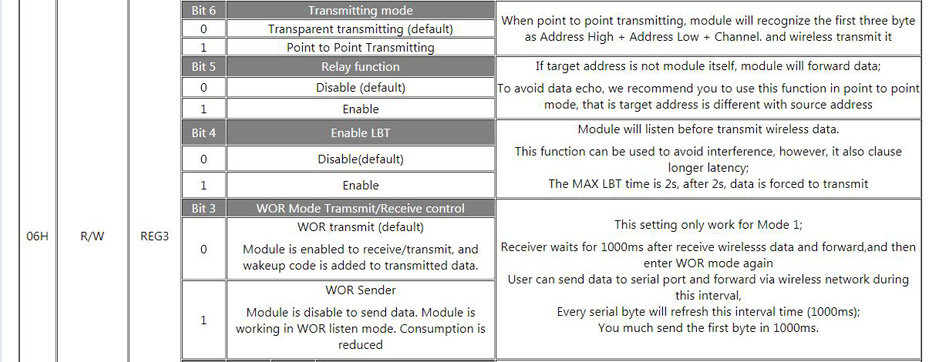
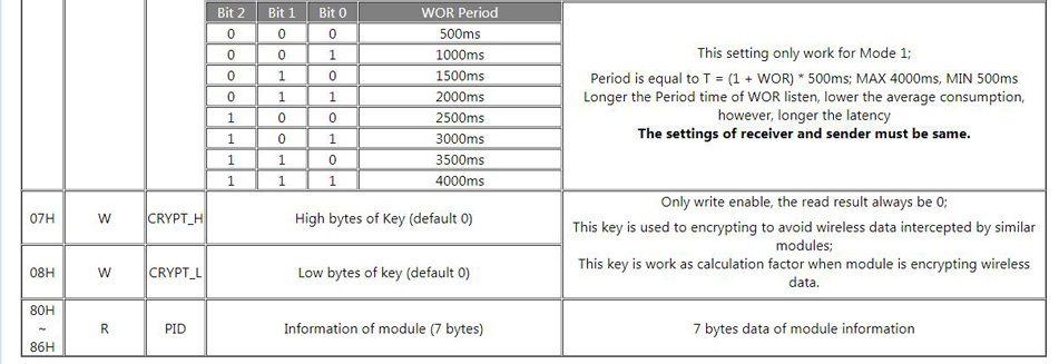
Registers Description

Debugging
- 1. To test, you need two SX1262 LoRa HAT (hereafter called LoRa HAT), two micro USB cables.
- 2. Connect SMA antennas to LoRa HATs. Set jumpers to A and set M0 and M1 to GND.
- 3. Connect USB to UART interfaces of two LoRa HATs to PC by micro USB cables
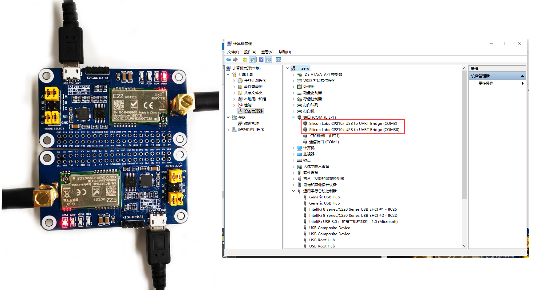
- 4. Check the COM ports on Devices Manager
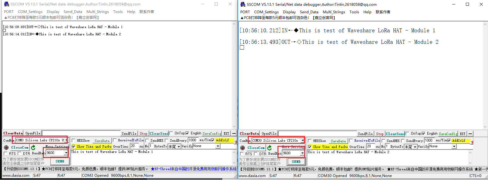
- 5. Open SSCOM software, Set serial ports to 9600, 8N1 and try to send data.
Using Examples
You can download the demo codes from #Demo codes
- Unzip the archive downloaded and get the codes as below:
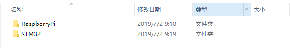
- Raspberry Pi examples
- To use Raspberry Pi examples, you need to copy the RaspberryPi to /boot/ directory of Raspbian (OS of Raspberry Pi) first, then move it to /home/pi directory of Raspbian
1. Hardware connection
- To test the codes, you need to setup two devices with one RaspberryPi board and two LoRa HAT.
- Add one LoRa HAT on Raspberry Pi (device 1), then set jumpers to B and remove M0, M1 jumpers
- Connect another LoRa HAT to PC(device 2), then set jumpers to A and set M0 and M1 to GND refer to #Debugging
- Powering on Raspberry Pi

2. Enable serial port
- Open Terminal of Raspberry Pi
- Run command sudo raspi-config to open Configure interface
- Choose Interfacing Options -> Serial -> No -> Yes
3. Install libraries
- There are libraries should be installed ahead
sudo apt-get install python-pip
sudo pip install RPi.GPIO
sudo apt-get install python-smbus
sudo apt-get install python-serial
4. Transparent communicating
- Enter directory of transparent example
cd ~/RaspberryPi/transparent
- Run code
sudo python transparent.py BROADCAST_AND_MONITOR

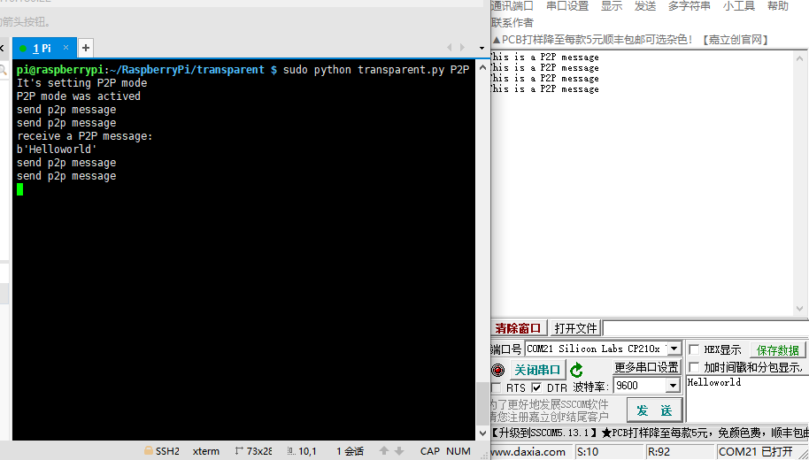
- You can also use command P2P to do Point to Point communicating
sudo python transparent.py P2P
sudo apt-get install python-pip sudo pip install RPi.GPIO sudo apt-get install python-smbus sudo apt-get install python-serial
- 5. Relay example
Relay communicating is one of ultra-long distance communicating. In Relay mode, address register of LoRa HAT is used to NETID forward and pair instead of auto receiving/transmitting, low consumption operation could not be done either.
【Note】 To test Relay example, you require at least three LoRa HATs.
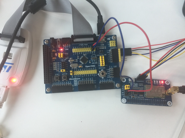
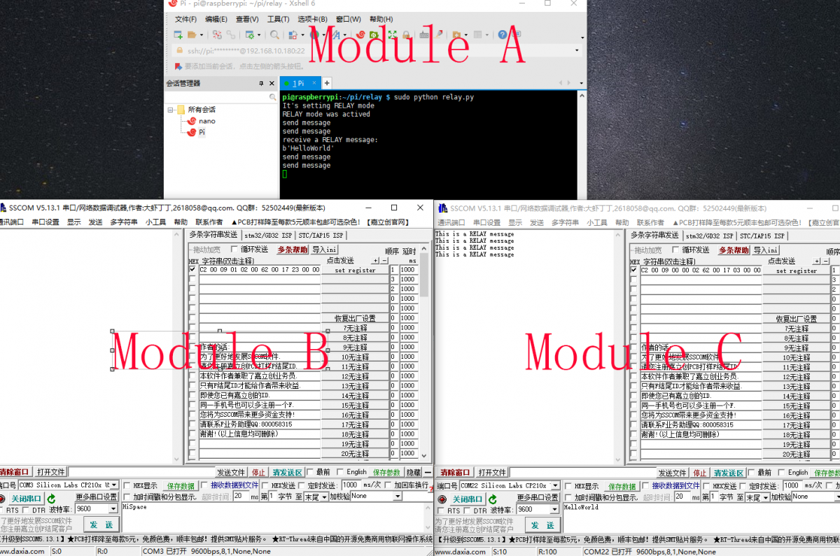
- Take the first three LoRa HATs as LoRa A, LoRa B and LoRa C
- Connect LoRa B to PC, and set it to Relay mode.That is set M0 to GND and disconnect M1 then configure ADDH register to 0x01, ADDL to 0x02, REG3 to 0x23 by command: C1 00 09 01 02 00 62 00 12 23 00 00 (HEX). After configuring, connect M1 and M0 to GND.
- Connect LoRa C to PC and set it as end note. That is set M1 to GND and disconnect M1, then configure ADDH register to 0x03, ADDL to 0x04, NETID to 0x04 by command: C1 00 09 00 00 02 62 00 12 03 00 00 (HEX). After configuring, connect M1 and M0 to GND
- Add LoRa A to Raspberry Pi, set jumpers to A and disconnect M1, M0.
- Enter directory of relay example. run the codes
cd ~/RaspberryPi/relay
sudo python relay.py
6. WOR example
Consumption of LoRa HAT is low when working in WOR mode. In WOR mode, data communication has latency, can be powered by batteries because of low consumption.
To test WOR example, two LoRa HATs are required.
- Add LoRa HAT on Raspberry Pi and set jumpers to B, disconnect M1 and M0.
- Connect LoRa HAT to PC and set it to WOR mode. You need to set M1 to GND and disconnect M1 before configuring and connect M1 to GND, diconnect M0 after configuring. (Device 1)
- Enter directory of WOR example and run it
cd ~RaspberryPi/wor
sudo python wor.py
- The data transmitted by Pi (device 1)will be received by PC (device 2) with delay.
- STM32
The examples for STM32 are based on Open103C (STM32F103CBT6). Use HAL Lib.
1. Hardware connection
Set jumpers to B, and connect LoRa HAT to STM32 board pins by pins:
SX1262 LoRa HAT STM32 5V 5V GND GND RXD PA10 TXD PA9 M1 PB15 M0 PB14
2. Expected result
The connection of other LoRa HATs (if required) you can refer to the Raspberry Pi example parts.
- Open the project, and modify the definition on main.c file for different communicating modes
#define TRASNSPARENT
//#define RELAY
//#define WOR
Relay communicating is one of ultra-long distance communicating. In Relay mode, address register of LoRa HAT is used to NETID forward and pair instead of auto receiving/transmitting, low consumption operation could not be done either.
cd ~/RaspberryPi/relay sudo python relay.py
cd ~RaspberryPi/wor sudo python wor.py
#define TRASNSPARENT //#define RELAY //#define WOR