


- sales/support
Google Chat: zj734465502@gmail.com
- sales
+86-0755-88291180
- sales01
sales01@spotpear.com
- sales02
dragon_manager@163.com
- support
services01@spotpear.com
- CEO-Complaints
manager01@spotpear.com
- sales/support
WhatsApp:13246739196
- HOME
- >
- ARTICLES
- >
- Common Moudle
- >
- ESP
ESP32-S3-Touch-LCD-4.3 Guide
Resource
Document
Demo
Software
Datasheet
Overview
Introduction
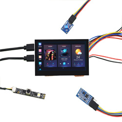
ESP32-S3-Touch-LCD-4.3 is a microcontroller development board with 2.4GHz WiFi and BLE 5 support, and integrates high-capacity Flash and PSRAM. The onboard 4.3-inch capacitive touch screen can smoothly run GUI programs such as LVGL. Combined with various peripheral interfaces, it is suitable for the quick development of the HMI and other ESP32-S3 applications.
Features
- Equipped with Xtensa 32-bit LX7 dual-core processor, up to 240MHz main frequency.
- Supports 2.4GHz Wi-Fi (802.11 b/g/n) and Bluetooth 5 (LE), with an onboard antenna.
- Built-in 512KB of SRAM and 384KB ROM, with onboard 8MB PSRAM and 8MB Flash.
- Onboard 4.3inch capacitive touch display, 800×480 resolution, 65K color.
- Supports capacitive touch control via I2C interface, 5-point touch with interrupt support.
- Onboard CAN, RS485, I2C interface, and TF card slot, integrate full-speed USB port.
- Supports flexible clock, module power supply independent setting, and other controls to realize low power consumption in different scenarios.
Hardware Description
Onboard Interface
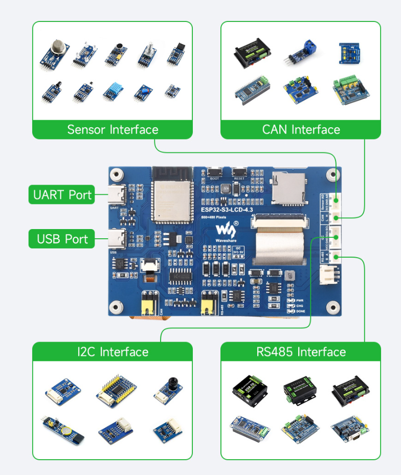
- UART interface: Using CH343P chip for USB to UART to connect to ESP32-S3's UART_TXD(GPIO43) and UART_RXD(GPIO44), enabling firmware burning and log printing.
- USB interface: GPIO19(DP) and GPIO20(DN) are the USB pins of ESP32-S3 by default, and the interface can be used for connecting cameras with protocols such as UVC. Please click here to view the UVC driver.
- Sensor interface: this interface is for connecting GPIO6 as ADC, and can be connected to sensors.
- CAN interface: The CAN interface pins and USB interface pins share a multiplexed function, utilizing the FSUSB42UMX chip for switching. By default, the USB interface is used (when the USB_SEL pin of FSUSB42UMX is set to HIGH).
- I2C interface: ESP32-S3 offers multiple hardware I2C interfaces. Currently, GPIO8 (SDA) and GPIO9 (SCL) pins are used as the I2C bus to connect to the IO expansion chip, touch interfaces, and other I2C peripherals.
- RS485 interface: The development board is equipped with an onboard RS485 interface circuit, allowing direct communication with RS485 devices. The RS485 circuit automatically switches between transmit and receive modes.
- PH2.0 battery header: The development board employs the efficient charging and discharging management chip CS8501, capable of boosting a single lithium battery to 5V. Currently, the charging current is set at 580mA. Users can modify the charging current by replacing the R45 resistor. For further details, please refer to the schematic diagram.
| ESP32-S3-WROOM-x | LCD | USB | SD | UART | CAN | Sensor | |
| GPIO0 | G3 | ||||||
| GPIO1 | R3 | ||||||
| GPIO2 | R4 | ||||||
| GPIO3 | VSYNC | ||||||
| GPIO4 | TP_IRQ | ||||||
| GPIO5 | DE | ||||||
| GPIO6 | AD | ||||||
| GPIO7 | PCLK | ||||||
| GPIO8 | TP_SDA | ||||||
| GPIO9 | TP_SCL | ||||||
| GPIO10 | B7 | ||||||
| GPIO11 | MOSI | ||||||
| GPIO12 | SCK | ||||||
| GPIO13 | MISO | ||||||
| GPIO14 | B3 | ||||||
| GPIO15 | RS485_TX | ||||||
| GPIO16 | RS485_RX | ||||||
| GPIO17 | B6 | ||||||
| GPIO18 | B5 | ||||||
| GPIO19 | USB_DN | CANRX | |||||
|---|---|---|---|---|---|---|---|
| GPIO20 | USB_DP | CANTX | |||||
| GPIO21 | G7 | ||||||
| GPIO38 | B4 | ||||||
| GPIO39 | G2 | ||||||
| GPIO40 | R7 | ||||||
| GPIO41 | R6 | ||||||
| GPIO42 | R5 | ||||||
| GPIO43 | UART_TXD | ||||||
| GPIO44 | UART_RXD | ||||||
| GPIO45 | G4 | ||||||
| GPIO46 | HSYNC | ||||||
| GPIO47 | G6 | ||||||
| GPIO48 | G5 | ||||||
| CH422G | - | - | - | - | - | - | |
| EXIO1 | TP_RST | ||||||
| EXIO2 | DISP | ||||||
| EXIO3 | LCD_RST | ||||||
| EXIO4 | SD_CS | ||||||
| EXIO5 | USB_SEL(HIGH) | USB_SEL(LOW) |
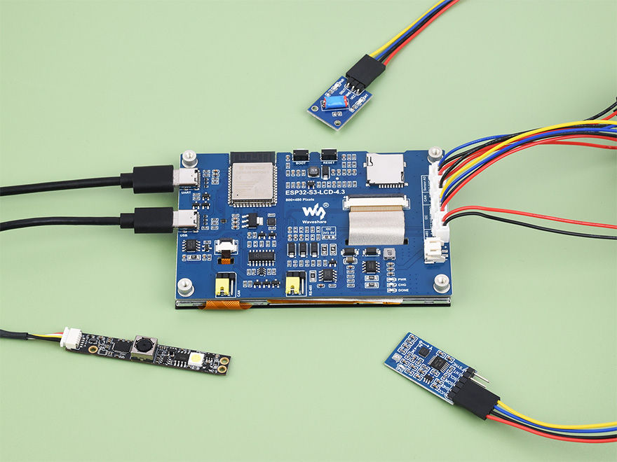
Hardware Connection
- ESP32-S3-Touch-LCD-4.3 comes with an onboard automatic download circuit. The Type C port, marked UART, is used for program downloads and logging. Once the program is downloaded, run it by pressing the RESET button.
- Please keep other metals or plastic material away from the PCB antenna area during use.
- The development board uses a PH2.0 connector to extend ADC, CAN, I2C, and RS485 peripheral pins. Utilize a PH2.0 to 2.54mm DuPont male connector to link sensor components.
- As the 4.3-inch screen occupies most GPIO pins, you can use a CH422G chip to expand IO for functions like reset and backlight control.
- The CAN and RS485 peripheral interfaces connect to a 120ohm resistor using jumper caps by default. Optionally, connect NC to cancel the termination resistor.
- The SD card employs SPI communication. Note that the SD_CS pin needs to be driven by the EXIO4 of the CH422G.
Other Notes
- The average frame rate for running the LVGL benchmark example on a single core in ESP-IDF v5.1 is 41 FPS. Before compilation, enabling 120M PSRAM is necessary.
- The PH2.0 lithium battery socket only supports a single 3.7V lithium battery. Do not use multiple sets of battery packs for charging and discharging simultaneously. It's recommended to use a single-cell battery with a capacity below 2000mAh.
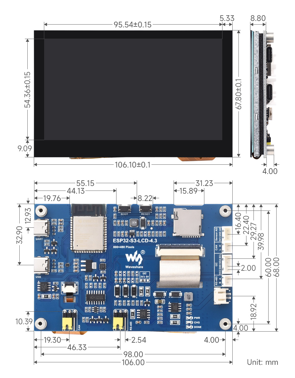
Dimensions
Environment Setting
The software framework for ESP32 series development boards is completed, and you can use CircuitPython, MicroPython, and C/C++ (Arduino, ESP-IDF) for rapid prototyping of product development. Here's a brief introduction to these three development approaches:
- Official C/C++ library installation:
- MicroPython is an efficient implementation of the Python 3 programming language. It includes a small subset of the Python standard library and has been optimized to run on microcontrollers and resource-constrained environments.
- You can refer to development documentation for MicroPython-related application development.
- The GitHub library for MicroPython allows for recompilation for custom development.
- Environment setting is supported on Windows 10. Users can select Arduino/Visual Studio Codes (ESP-IDF) as IDE to develop. For Mac/Linux, users can refer to official introduction.
ESP-IDF
Arduino
- Download and install Arduino IDE.
- Install ESP32 on the Arduino IDE as shown below, and you can refer to this link.
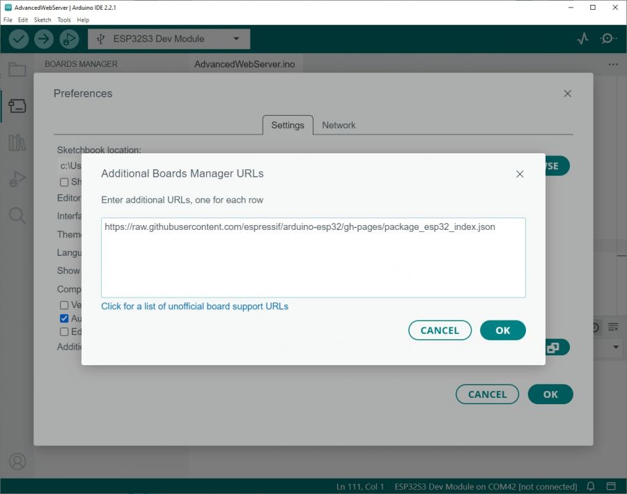
- Fill in the following link in the Additional Boards Manager URLs section of the Settings screen under File -> Preferences and save.
https://raw.githubusercontent.com/espressif/arduino-esp32/gh-pages/package_esp32_index.json
- Search esp32 on Board Manager to install, and restart Arduino IDE to take effect.
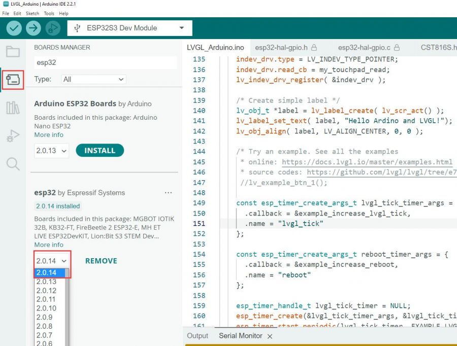
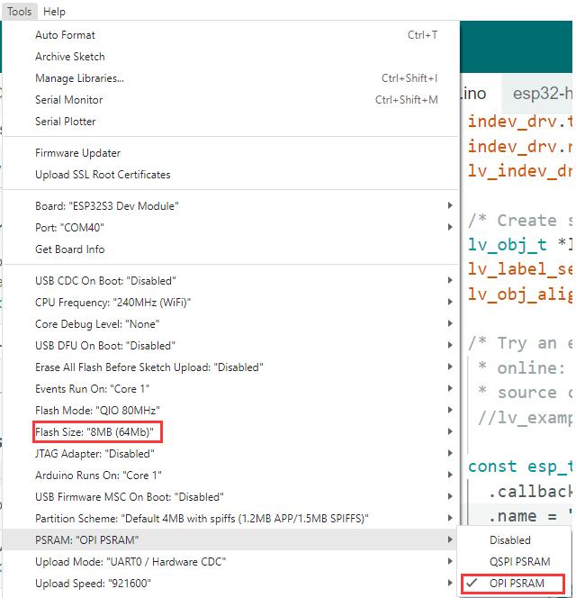
3. Open the Arduino IDE and note that Tools in the menu bar selects the corresponding Flash (8MB) and enables PSRAM (8MB OPI), as shown in the following figure.
Library Installation
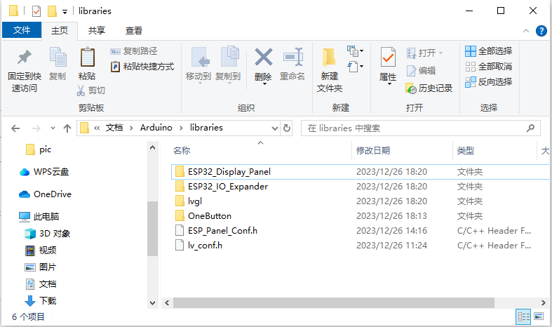
- TFT_SPI and lvgl libraries require configuration files after installation. It's recommended to directly use the ESP32_Display_Panel, ESP32_IO_Expander in the s3-4.3-libraries, and lvgl folders, along with the ESP_Panel_Conf.h and lv_conf.h files, and copy them to the directory C:\Users\xxxx\Documents\Arduino\libraries. Please note that "xxxx" represents your computer username.
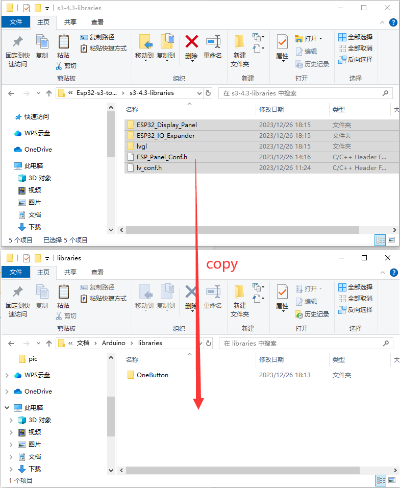
- After copying:
Sample Demo
Arduino
UART_Test
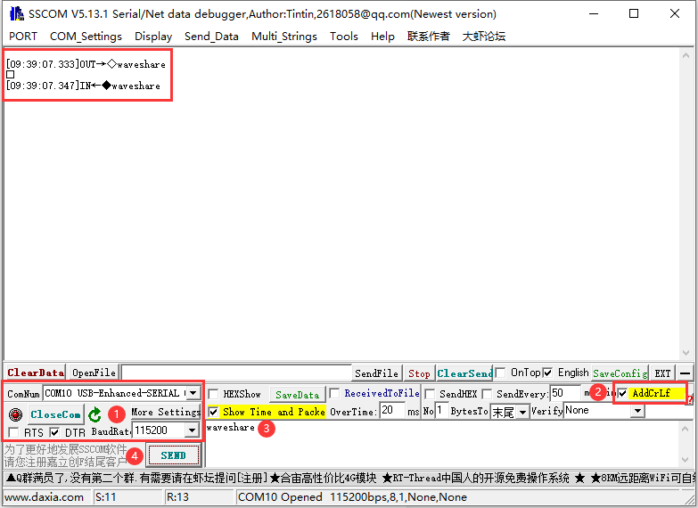
Take UART_Test as an example, UART_Test can be used for testing UART interface. This interface can connect to GPIO43(TXD) and GPIO44(RXD) as UART0.
- After programming the code, connect the USB to Type-C cable to the "UART" Type-C interface. Open the serial port debugging assistant, and send a message to ESP32-S3-Touch-LCD-4.3. ESP32-S3-Touch-LCD-4.3 will return the received message to the serial port debugging assistant. Note that you need to select the correct COM port and baud rate. Check "AddCrLf" before sending the message.
Sensor_AD
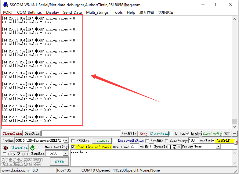
Sensor_AD example is used to test the usage of the Sensor AD socket. This interface connects to GPIO6 for ADC usage and can be connected to Sensor kits and so on.
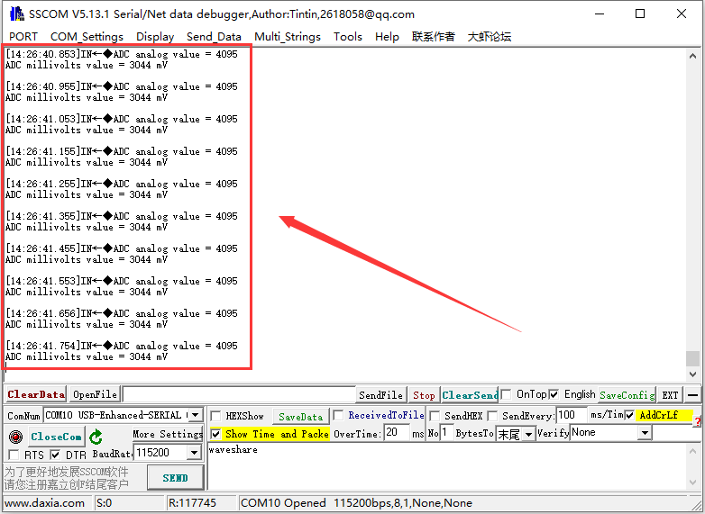
- After burning the code, connect the Sensor AD socket to "HY2.0 2P to DuPont male head 3P 10cm". You can then open the serial port debugging assistant to observe the data read from the AD pin. "ADC analog value" represents the analog value read from the ADC, while "ADC millivolts value" represents the ADC value converted to millivolts.
- When shorting the AD pin with the GND pin, the read value is as shown in the diagram below:
- When shorting the AD pin with the 3V3 pin, the read value is as shown in the figure below:
I2C_Test
I2C_Test example is for testing I2C socket, and this interface can connect to GPIO8(SDA) and GPIO9(SCL) for I2C communication.
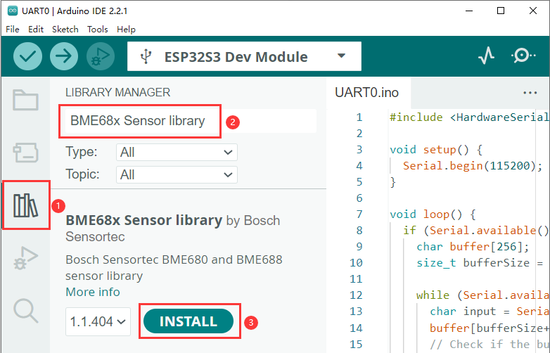
- Using this example for driving BME680 environment sensor, and before editing, you need to install the "BME68x Sensor library" through LIBRARY MANAGER.
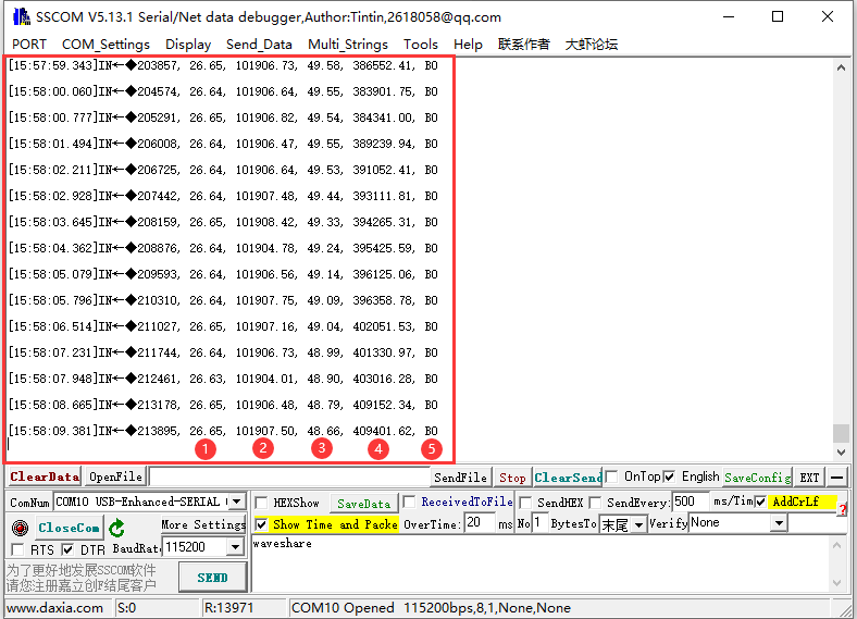
- After programming the code, the I2C socket is connected to "HY2.0 2P to DuPont male head 4P 10cm" and connected to the BME680 environmental sensor. This sensor is capable of detecting temperature, humidity, atmospheric pressure, and gas levels. By opening the serial port debugging assistant, you can observe: ① for temperature (°C), ② for atmospheric pressure (Pa), ③ for relative humidity (%RH), ④ for gas resistance (ohms), and ⑤ for the sensor's status.
RS485_Test
RS485_Test example is for testing RS-485 socket, and this interface can connect to GPIO15(TXD) and GPIO16(RXD) for RS485 communication.
- This demo require USB TO RS485 (B). After programming the code, the RS-485 socket can connect to USB TO RS485 (B) through a "HY2.0 2P to DuPont male head 2P 10cm" and then connect it to the PC.
- Open the serial port debugging assistant and send an RS485 message to ESP32-S3-Touch-LCD-4.3. The ESP32-S3-Touch-LCD-4.3 will return the received message to the serial port debugging assistant. Ensure to select the correct COM port and baud rate. Before sending the message, check "AddCrLf" to add a carriage return and line feed.

SD_Test
The SD_Test example is used to test the SD card socket. Before using it, insert an SD card.
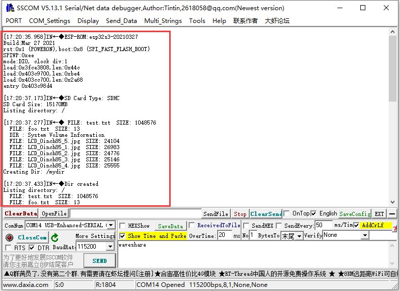
- After burning the code, the ESP32-S3-Touch-*LCD-4.3 will recognize the type and size of the SD card and proceed with file operations such as creating, deleting, modifying, and querying files.
TWAItransmit (CAN transmit)
TWAItransmit example is for testing CAN socket, and this interface can connect to GPIO20(TXD) and GPIO19(RXD) for CAN communication.
- After programming the code, using the "HY2.0 2P to DuPont male head 2P red-black 10cm" cable, and connect the CAN H and CAN L pins of the ESP32-S3-Touch-LCD-4.3 to the USB-CAN-A.
- Once you open the serial port debugging assistant, you should observe that the Esp32-s3-touch-lcd-4.3 has started sending CAN messages.
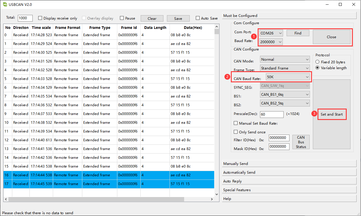
- Connect the USB-CAN-A to the computer and open the USB-CAN-A_TOOL_2.0 upper computer software. Select the corresponding COM port, set the baud rate to 2000000 as shown in the image, and set the CAN baud rate to 50.000Kbps. This configuration will allow you to view the CAN messages sent by the Esp32-s3-touch-lcd-4.3.
TWAIreceive (CAN receive)
TWAIreceive example is for testing CAN socket, and this interface can connect to GPIO20(TXD) and GPIO19(RXD) for CAN communication.
- After uploading the code, use the "HY2.0 2P to DuPont male head 2P red-black 10cm" cable to connect the CAN H and CAN L pins of the ESP32-S3-Touch-LCD-4.3 to the USB-CAN-A.
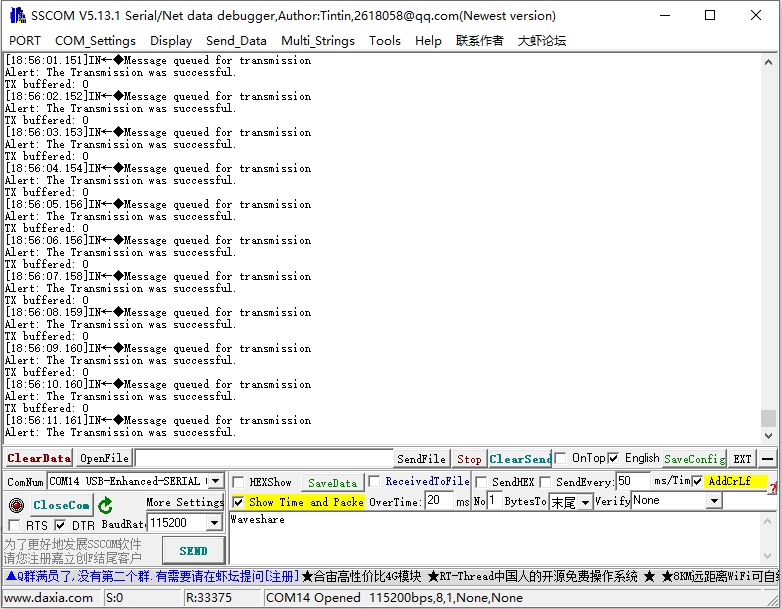
- Connect the USB-CAN-A to the computer and open the USB-CAN-A_TOOL_2.0 upper computer software. Select the corresponding COM port, set the port baud rate to 2000000 as indicated in the image, and set the CAN baud rate to 500.000Kbps. With these settings, you'll be able to send CAN messages to the Esp32-s3-touch-lcd-4.3.
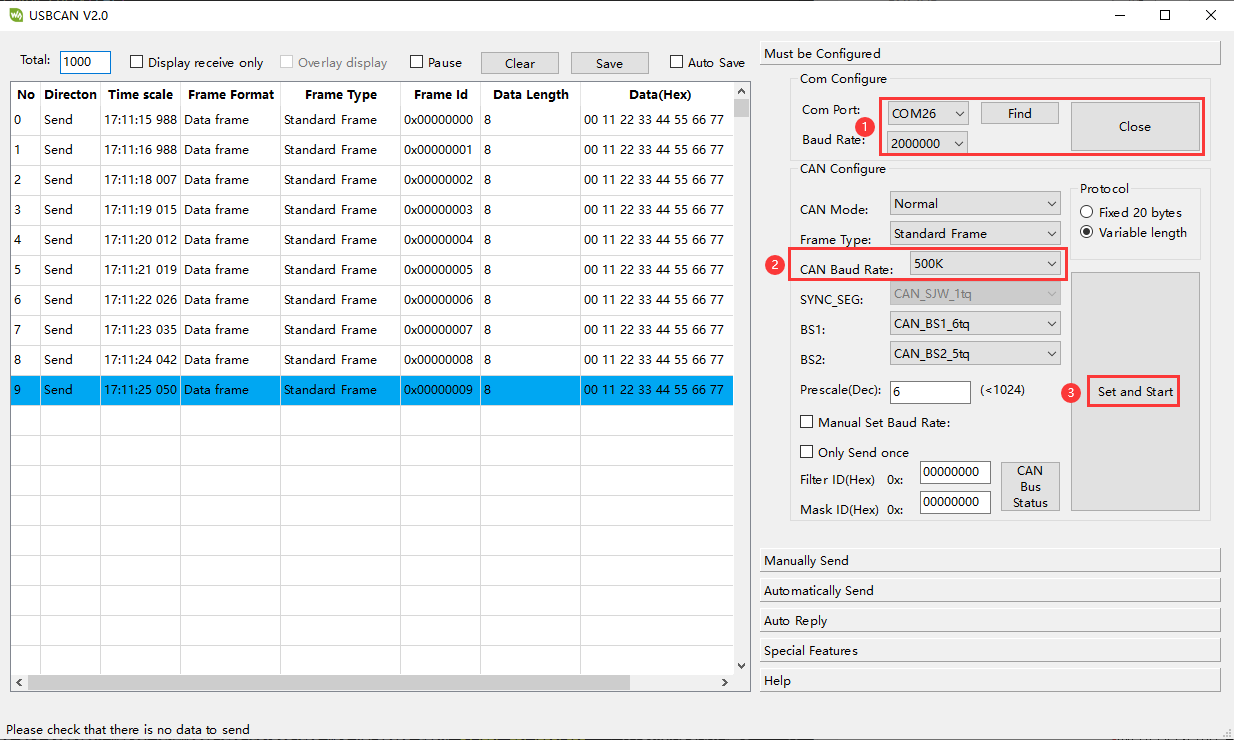
- Open the serial port debugging assistant, and you should observe that the Esp32-s3-touch-lcd-4.3 has started receiving CAN messages. If there are any reception errors, try resetting the devices multiple times and restarting the software. Please be patient and allow some time for the reception process.
lvgl_Porting
lvgl_Porting example is for testing RGB touch screen.
- After uploading the code, you can try to touch it. Also, we provide LVGL porting examples for users (If there's no screen response after burning the code, check if the Arduino IDE -> Tools settings are correctly configured: choose the corresponding Flash (8MB) and enable PSRAM (8MB OPI)).
DrawColorBar
DrawColorBar example is for testing RGB screen.
- After uploading the code, you should observe the screen displaying bands of blue, green, and red colors. If the screen shows no response after burning the code, check if the Arduino IDE -> Tools settings are correctly configured: choose the corresponding Flash (8MB) and enable PSRAM (8MB OPI).
ESP-IDF
esp32-s3-lcd-4.3-b-i2c_tools
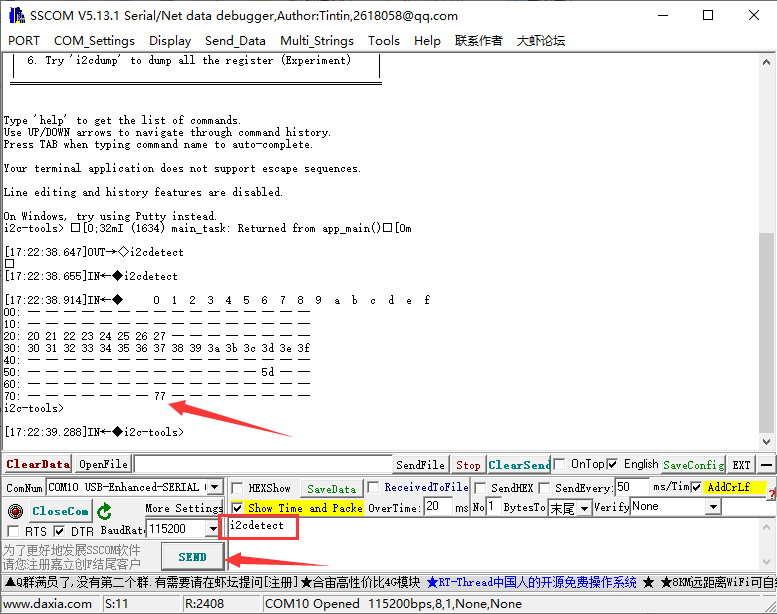
- esp32-s3-lcd-4.3-b-i2c_tools example is used to test the I2C socket by scanning various I2C device addresses.
- After uploading the code, connect the I2C device (for this example, we're using the BME680 Environmental Sensor) to the corresponding pins on the ESP32-S3-Touch-LCD-4.3. Open the serial port debugging assistant, select a baud rate of 115200, and open the corresponding COM port for communication (make sure to disable ESP-IDF's COM port first, as it might occupy the COM port and prevent serial port access).
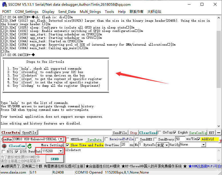
- Press the Reset key of the ESP32-S3-Touch-LCD-4.3, SSCOM prints message, input "i2cdetect" as shown below. "77" is printed, and the I2C socket test passes.
uart_echo
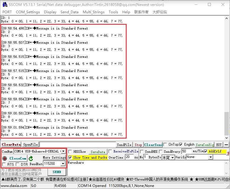
uart_echo example is for testing RS485 socket.
- After uploading the code, connect the USB TO RS485 and ESP32-S3-Touch-LCD-4.3 through A and B pins. Open SSCOM to select the corresponding COM port for communication after connecting USB TO RS485 to the PC.
- Select the baud rate as 115200 as shown below. When you send any character, it gets looped back and displayed. That's a good indication that the RS485 socket is working as expected.

twai_network_master
twai_network_master example is for testing CAN socket.
- After uploading the code, use the "HY2.0 2P to DuPont male head 2P red-black 10cm" cable to connect the CAN H and CAN L pins of the ESP32-S3-Touch-LCD-4.3 to the USB-CAN-A.
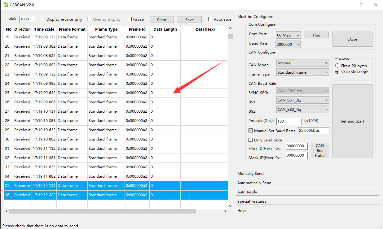
- Connect the USB-CAN-A to the computer and open the USB-CAN-A_TOOL_2.0 upper computer software. Select the corresponding COM port, set the port baud rate to 2000000 as shown in the image, and set a custom baud rate of 25.000Kbps (adjusting phase buffer 1 and phase buffer 2 if necessary).
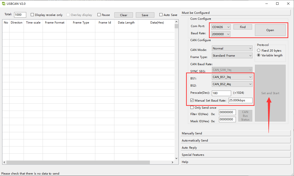
- Pressing the Reset button on the ESP32-S3-Touch-LCD-4.3 causes data to be printed in the data field of USBCANV2.0, confirming the successful test of the CAN socket.
demo1
demo1 example is for testing the display effect of the screen.