- sales/support
Google Chat: zj734465502@gmail.com
- sales
+86-0755-88291180
- sales01
sales01@spotpear.com
- sales02
dragon_manager@163.com
- support
services01@spotpear.com
- CEO-Complaints
manager01@spotpear.com
- sales/support
WhatsApp:13246739196
- HOME
- >
- ARTICLES
- >
- Common Moudle
- >
- UART Module
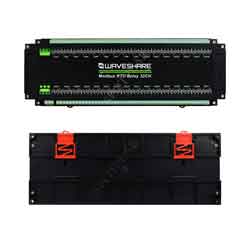
Modbus RTU Relay 32CH User Guide
Demo
Software
Hardware Test
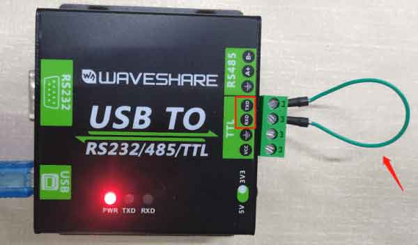
RS485 Test
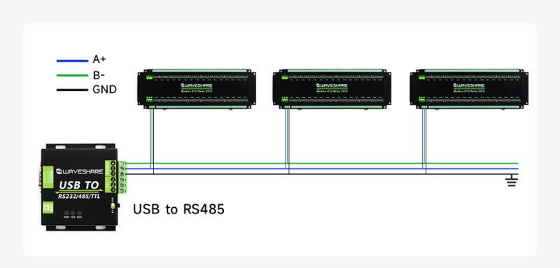
- Connect USB TO 485 and the target board with cables, and connect A --> A and B --> B as shown below:
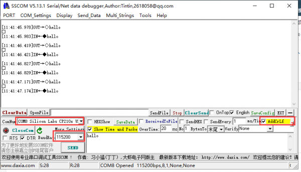
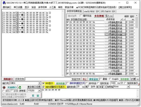
- Download SSCOM and open it on the computer, open the corresponding port number, and set the baud rate as 9600. Clicking on multiple strings will open multiple string-sending windows. Clicking on the corresponding function will send the corresponding command.
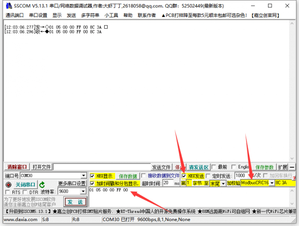
- If you need to send other commands then select HEX send, plus check select ModbusCRC16 checksum, enter the first six bytes of the command and click send then the CRC checksum will be added automatically.
- For detailed control commands, please see the development protocol.
Demo Test
Note: RS485 cannot be directly connected to the serial port of the Raspberry Pi, as it may damage the device. A 485-level converter is required. It is recommended to use the Raspberry Pi with an RS485 CAN HAT module. For NUCLEO-F103RB and Arduino, it is recommended to use an RS485 CAN Shield module.
Raspberry Pi
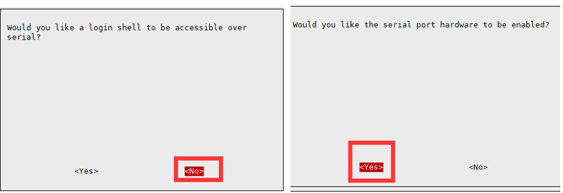
Open the terminal of the Raspberry Pi, and input the following commands to enter the configure interface:
sudo raspi-config
Choose Interfacing Options -> Serial, disable shell visit, open the hardware serial port
And then reboot the Raspberry Pi:
sudo reboot
Open /boot/config.txt file, and find the following configure sentences to enable the serial port. If there is none, you can add it at the end of the file:
enable_uart=1
For Raspberry Pi 3B users, the serial port is for Bluetooth, and you need to comment it out.
#dtoverlay=pi3-miniuart-bt
And then reboot the Raspberry Pi:
sudo reboot
Insert the RS485 CAN HAT into the Raspberry Pi and connect the A and B terminals of the Modbus RTU Relay module to the corresponding terminals of the RS485 CAN HAT module. If you are using other RS485 devices, make sure to connect A to A and B to B.
Run the following commands:
sudo apt-get install unzip
wget https://www.waveshare.com/w/upload/7/74/Modbus_RTU_Relay_32CH_Code.zip
unzip Modbus_RTU_Relay_32CH_Code.zip
cd Modbus_RTU_Relay_32CH_Code/Python3
sudo python3 main.py
STM32
The STM32 demo is based on the NUCLEO-F103RB and the RS485 CAN Shield module.
Find the STM32 demo file directory and open the STM32 project. Make sure the keil5 software is installed on your computer before use, and download the demo to the development board.
Normal operation on the relay module will open and then close sequentially. The serial port will output the sent command.
Arduino
The Arduino demo is based on NUO PLUS and RS485 CAN Shield module.
Use Arduino IDE to open the demo and choose the corresponding development board to download the demo.
Normal operation on the relay module will open and then close sequentially. The serial port will output the sent command.
Development Protocol
Function Code
| FUNC | NOTE |
|---|---|
| 01 | Read the relay status |
| 03 | Read the address and version |
| 05 | Write a single relay |
| 06 | Set the baud rate and address |
| 0F | Write all relays |
Single Relay Control
Sending code: 01 05 00 00 FF 00 8C 3A
| Fields | Meaning | Remarks |
|---|---|---|
| 01 | Device Address | 0x00 for broadcast address; 0x01-0xFF for device address |
| 05 | 05 Command | Control the relay |
| 00 00 | Address | Register address of the relay to be controlled, 0x00 - 0x001F |
| FF 00 | Command | 0xFF00: relay on 0x0000: relay off 0x5500: relay flip |
| 8C 3A | CRC16 | CRC16 checksum of the first 6 bytes of data |
Return code: 01 05 00 00 FF 00 8C 3A
| Fields | Meaning | Remarks |
|---|---|---|
| 01 | Device Address | 0x00 for broadcast address; 0x01-0xFF for device address |
| 05 | 05 Command | Control the relay |
| 00 00 | Address | Register address of the relay to be controlled, 0x0000-0x001F |
| FF 00 | Command | 0xFF00: relay on; 0x0000: relay off; 0x5500: relay flip |
| 8C 3A | CRC16 | CRC16 checksum of the first 6 bytes of data |
For example: [NO. 1 address device]:
NO. 0 relay on: 01 05 00 00 FF 00 8C 3A
NO. 0 relay off: 01 05 00 00 00 00 CD CA
NO. 1 relay on: 01 05 00 01 FF 00 DD FA
NO. 1 relay off: 01 05 00 01 00 00 9C 0A
NO. 2 relay on: 01 05 00 02 FF 00 2D FA
NO. 2 relay off: 01 05 00 02 00 00 6C 0A
NO. 3 relay on: 01 05 00 03 FF 00 7C 3A
NO. 3 relay off: 01 05 00 03 00 00 3D CA
NO. 0 relay flip: 01 05 00 00 55 00 F2 9A
NO. 1 relay flip: 01 05 00 01 55 00 A3 5A
NO. 2 relay flip: 01 05 00 02 55 00 53 5A
NO. 3 relay flip: 01 05 00 03 55 00 02 9A
Read Relay Status
Sending code: 01 01 00 00 00 20 3D D2
| Fields | Meaning | Remarks |
|---|---|---|
| 01 | Device Address | 0x00 for broadcast address; 0x01-0xFF for device address |
| 01 | 01 Command | Query relay status command |
| 00 00 | Relay Start Address | Fixed 0x0000 |
| 00 10 | Relay Numbers | Fixed 0x0020 |
| 3D D2 | CRC16 | CRC16 checksum of the first 6 bytes of data |
Return code: 01 01 04 00 00 00 00 FB D1
| Fields | Meaning | Remarks |
|---|---|---|
| 01 | Device Address | 0x00 for broadcast address; 0x01-0xFF for device address |
| 01 | 01 Command | Query relay status command |
| 02 | Bytes | Returns all bytes of the status message |
| 00 00 00 00 | Query status | Returned relay status Bit0: the first relay status; Bit1: the second relay status; Bit2: the third relay status; …… Bit31: the 32th relay status |
| FB D1 | CRC16 | CRC16 checksum of the first 6 bytes of data |
For example:
[NO.1 address device]
Send: 01 01 00 00 00 20 3D D2
Return: 01 01 04 00 00 00 00 FB D1 //All relays off
Send: 01 01 00 00 00 20 3D D2
Return: 01 01 04 00 00 00 01 3A 11 //NO.0 relay on, others off
Send: 01 01 00 00 00 20 3D D2
Return: 01 01 04 00 00 00 41 3B E1 //NO.0 and NO.6 relays on, others off
Write Relay Status
Sending code: 01 0F 00 00 00 20 04 FF FF FF FF C5 1C
| Field | Meaning | Note |
|---|---|---|
| 01 | Device Address | 0x00 for broadcast address; 0x01-0xFF for device address |
| 0F | 0F Command | Write relay status command |
| 00 00 | Relay Start Address | Fixed 0x0000 |
| 00 20 | Relay Numbers | Fixed 0x0020 |
| 04 | Byte Number | Fixed 0x04 |
| FF FF FF FF | Relay Status | Bit0: control the first relay; Bit1: control the second relay; Bit2: control the third relay; …… Bit31: control 31th relay; |
| C5 1C | CRC16 | CRC16 checksum of the first 6 bytes of data |
Return code: 01 0F 00 00 00 20 54 13
| Fields | Meaning | Remarks |
|---|---|---|
| 01 | Device Address | 0x00 for broadcast address; 0x01-0xFF for device address |
| 0F | 0F Command | Control all relays command |
| 00 00 | Address | Fixed 0x0000 |
| 00 20 | Relay Numbers | Fixed 0x0010 |
| 54 13 | CRC16 | CRC16 checksum of the first 6 bytes of data |
For example:
[No. 1 address device]
All relays on: 01 0F 00 00 00 20 04 FF FF FF FF C5 1C
All relays off: 01 0F 00 00 00 20 04 00 00 00 00 C4 88
0-1 on; 3-15 off: 01 0F 00 00 00 20 04 00 00 00 03 84 89
Relay Flash On Flash Off Command
Sending code: 01 05 02 00 00 07 8D B0
| Fields | Meaning | Remarks |
|---|---|---|
| 01 | Device Address | 0x00 for broadcast address; 0x01-0xFF for device address |
| 05 | 05 Command | Single control command |
| 02 | Command | 02 is a flash-on command, and 04 is a flash-off command. |
| 00 | Relay Address | address of the relay to be controlled, 0x00~0x1F |
| 00 07 | Interval Time | The delay time is data *100ms Value: 0x0007, Delay: 7*100MS = 700MS |
| 8D B0 | CRC16 | CRC16 checksum of the first 6 bytes of data |
Return code: 01 05 02 00 00 07 8D B0
| Fields | Meaning | Remarks |
|---|---|---|
| 01 | Device Address | 0x00 for broadcast address; 0x01-0xFF for device address |
| 05 | 05 Command | Single control command |
| 02 | Command | 02 is a flash-on command, 04 is a flash-off command |
| 00 | Relay Address | To control the relay address, 0x00~0x1F |
| 00 07 | Interval Time | Delay time: data*100ms Value: 0x0007, delay: 7*100MS = 700MS |
| 8D B0 | CRC16 | CRC16 checksum of the first 6 bytes of data |
Remarks:
The maximum setting for the flash-on flash-off time is 0x7FFF.
For example:
[NO.1 address device]
NO.0 relay flash on: 01 05 02 00 00 07 8D B0 //700MS = 7*100MS = 700MS
NO.1 relay flash on: 01 05 02 01 00 08 9C 74 //800MS
NO.0 relay flash off: 01 05 04 00 00 05 0C F9 //500MS
NO.1 relay flash off: 01 05 04 01 00 06 1D 38 //600MS
Baudrate Setting Command
Sending code: 00 06 20 00 00 05 43 D8
| Fields | Meaning | Remarks |
|---|---|---|
| 00 | Device Address | 0x00 for broadcast address; 0x01-0xFF for device address |
| 06 | 06 Command | Baudrate setting, device address |
| 20 00 | Command Register | 0x2000 to set the baud rate, 0x4000 to set the device address |
| 00 | Parity | 0x00 for no parity, 0x01 for even check, 0x02 for odd parity |
| 05 | Baudrate | Corresponding baudrate: 0x00: 4800 0x01: 9600 0x02: 19200 0x03: 38400 0x04: 57600 0x05: 115200 0x06: 128000 0x07: 256000 |
| 43 D8 | CRC16 | CRC16 checksum of the first 6 bytes of data |
Return code: 00 06 20 00 00 05 43 D8
| Fields | Meaning | Remarks |
|---|---|---|
| 00 | Device Address | 0x00 for broadcast address; 0x01-0xFF for device address |
| 06 | 06 Command | set the baudrate and device address |
| 20 00 | Command Register | 0x2000 is to set the baudrate, and 0x4000 is to set the device address |
| 00 | Parity | 0x00 for broadcast address; 0x01-0xFF for device address |
| 05 | Baudrate | Corresponding baudrate: 0x00: 4800 0x01: 9600 0x02: 19200 0x03: 38400 0x04: 57600 0x05: 115200 0x06: 128000 0x07: 256000 |
| 43 D8 | CRC16 | CRC16 checksum of the first 6 bytes of data |
For example:
[NO.1 address device]
Set the baudrate as 4800: 00 06 20 00 00 00 83 DB
Set the baudrate as 9600: 00 06 20 00 00 01 42 1B
Set the baudrate as 115200: 00 06 20 00 00 05 43 D8
Device Address Setting Command
Sending code: 00 06 40 00 00 01 5C 1B
| Fields | Meaning | Remarks |
|---|---|---|
| 00 | Device Address | 0x00 for broadcast address; 0x01-0xFF for device address |
| 06 | 06 Command | Set the baudrate and device address |
| 40 00 | Command Register | 0x2000 for setting the baudrate, 0x4000 for setting device address |
| 00 01 | Device Address | Set the device address,0x0001-0x00FF |
| 5C 1B | CRC16 | CRC16 checksum of the first 6 bytes of data |
Return code: 00 06 40 00 00 01 5C 1B
| Fields | Meaning | Remarks |
|---|---|---|
| 00 | Device Address | 0x00 for broadcast address; 0x01-0xFF for device address |
| 06 | 06 Command | Set the baudrate and the device address |
| 40 00 | Command Register | 0x2000 is for setting the baudrate, 0x4000 is for setting the device address |
| 00 01 | Device Address | Set the device address, 0x0001-0x00FF |
| 5C 1B | CRC16 | CRC16 checksum of the first 6 bytes of data |
For example:
[NO.1 address device]
Set the device address as 0x01: 00 06 40 00 00 01 5C 1b
Set the device address as 0x02: 00 06 40 00 00 02 1C 1A
Set the device address as 0x03: 00 06 40 00 00 03 DD DA
Read the Device Address Command
Sending code: 00 03 40 00 00 01 90 1B
| Field | Meaning | Note |
|---|---|---|
| 00 | Device Address | 0x00 for broadcast address; 0x01-0xFF for device address |
| 03 | 03 Command | read the device address command |
| 40 00 | Command Register | 0x0200 for reading software version, 0x0040 for reading device address |
| 00 01 | Byte Numbers | Fixed 0x0001 |
| 90 1B | CRC16 | CRC16 checksum of the first 6 bytes of data |
Return code: 01 03 02 00 01 79 84
| Field | Meaning | Remarks |
|---|---|---|
| 00 | Device Address | 0x00 for broadcast address; 0x01-0xFF for device address |
| 03 | 03 Command | Read the software version and the device address |
| 02 | Bytes Number | Returned bytes |
| 00 01 | Device Address | Set the device address, 0x0001-0x00FF |
| 79 84 | CRC16 | CRC16 checksum of the first 6 bytes of data |
For example:
[NO.1 address device]
Send: 00 03 40 00 00 01 90 1B
Return: 01 03 02 00 01 79 84 //Address: 0x01
[NO.2 address device]
Send: 00 03 40 00 00 01 90 1B
Return: 02 03 02 00 02 7D 85 //Address: 0x02
[NO.3 address device]
Send: 00 03 40 00 00 01 90 1B
Return: 03 03 02 00 03 81 85 //Address: 0x03
Read the Software Version Command
Sending code: 00 03 80 00 00 01 AC 1B
| Fields | Meaning | Remarks |
|---|---|---|
| 01 | Device Address | 0x00 for broadcast address, 0x01-0xFF for device address |
| 03 | 03 Command | Read software version, read device address command |
| 80 00 | Command Register | 0x4000 for read device address, 0x8000 for read software version |
| 00 01 | Bytes | Fixed 0x0001 |
| 8F CA | CRC16 | CRC16 checksum of the first 6 bytes of data |
Return code: 01 03 02 00 64 B9 AF
| Fields | Meaning | Remarks |
|---|---|---|
| 01 | Device Address | 0x00 for broadcast address; 0x01-0xFF for device address |
| 03 | 03 Command | Read the software version and the device address |
| 02 | Bytes Number | Returned bytes number |
| 00 64 | Software Version | Converting to decimal and shifting the decimal point two places to the left indicates the software version
|
| B9 AF | CRC16 | CRC16 checksum of the first 6 bytes of data |
For example:
Send: 00 03 80 00 00 01 AC 1B
Return: 01 03 02 00 64 B9 AF //0x0064 = 100 =V1.00