


- sales/support
Google Chat:---
- sales
+86-0755-88291180
- sales01
sales@spotpear.com
- sales02
dragon_manager@163.com
- support
tech-support@spotpear.com
- CEO-Complaints
zhoujie@spotpear.com
- Only Tech-Support
WhatsApp:13246739196
- Purchase/Shipping/Refund
WhatsApp:13424403025
Chapter 10 of KitiBot-Microbit: Ultrasonic Obstacle User Guide
Chapter 10 Ultrasonic Obstacle
In this chapter we talk about how to use ultrasonic sensor and use ultrasonic for obstacle.
Generally, our ears cannot hear sounds above 20 kHz (sound was generated by vibration, 10 kHz, which is equivalent to 20 thousand vibrations per second, which is 20,000 times). Sonic waves produced above 20 kHz are called "ultrasounds". Due to their amblyopia, bats flying at night emit such ultrasound. Bats rely mainly on ultrasound to locate any avoidable obstacle on their way. Sound waves are emitted by the bat's throat and received by their ears, according to the received sound waves. They can determine the position of the front object. Ultrasound sensor invention is based on the same method
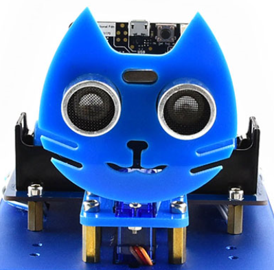
Ultrasonic sensor is mounted on the cat face, looks like two eyes of the cat, one eye is receiver and another is sender. With this ultrasonic sensor, Robot can detect the distance of obstacle in the front.
Read value of ultrasonic sensor
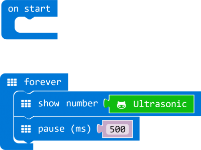
 : Using Ultrasonic block, we can read distance value (integer) from ultrasonic sensor.
We make a project to read ultrasonic value and display to LED matrix

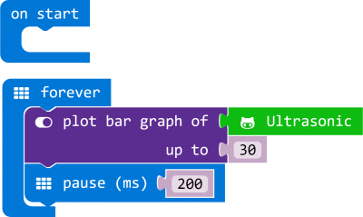
Show distance value with bar graph
Light more leds if obstacle is farer, less leds if closer
Obstacle detecting
We use ultrasonic sensor to detect obstacle and make robot stop when obstacle detected.
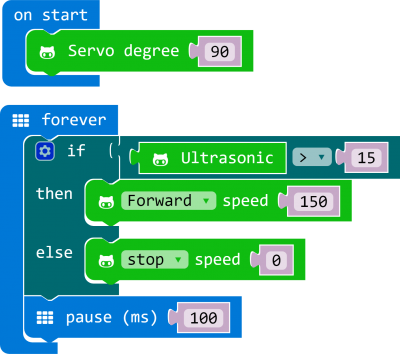
Ultrasonic sensor keeps detecting distance of obstacles in front, if distance is farer than 15cm, robot move forward, and stop if distance detected is less than 15cm. Note that you need to set servo degree to 90 on start, make sure ultrasonic sensor faces forward.
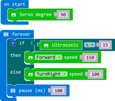
Turning when obstacle detected
We modify the code, let robot turn right when obstacle detected.
Turning according to distance
Here we add servo control code. Robot will rotate to both side to detect distance (obstacle) and turn to the farer side when obstacle is detected in front.
https://cdn.static.spotpear.com/uploads/picture/learn/micro-bit/micro-bit-kit/chapter-10-of-kitibot-microbit/chapter-10-of-kitibot-microbit-11.gif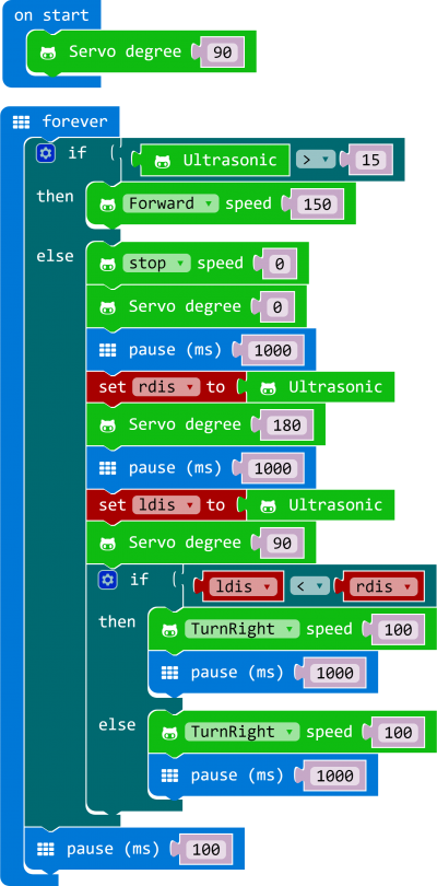
Variables rdis and ldis are used to save distances of right side and left side. By comparing rdis and ldis, robot can judge which side is farer. Pause are added because servo need times to rotate.