- sales/support
Google Chat: zj734465502@gmail.com
- sales
+86-0755-88291180
- sales01
sales01@spotpear.com
- sales02
dragon_manager@163.com
- support
services01@spotpear.com
- CEO-Complaints
manager01@spotpear.com
- sales/support
WhatsApp:13246739196
SIM7028 NB-IoT HAT User Guide
Schematic Diagram
Demo
Software
Introduction
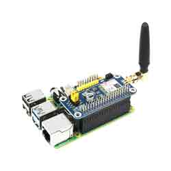
The SIM7028 NB-IoT HAT is an NB-IoT (Narrow-Band Internet of Things) development board for Raspberry Pi. It is designed for applications that need low delay, low power, and low throughput, also suitable for IoT applications such as meters, remote control, asset tracking, remote monitoring, remote healthcare, bicycle-sharing, and so on.
Features
- Compatible with Raspberry Pi Zero/Zero 2/2B/3B/3B+/4B.
- Supports TCP, UDP, LWM2M, COAP, DTLS, DNS, NTP, PING, HTTP(S), MQTT(S), TLS/SSL, etc.
- Onboard Type-C interface for software debugging.
- Onboard UART control pins for AR command transmission and firmware update.
- Onboard control pins for connecting with host boards like Arduino/STM32.
- Onboard USB to UART chip, the UART communication pin can be configured via jumper.
- Onboard nano SIM card slot, compatible with NB-IoT-specific card.
- 1x LED indicator, easy to monitor the working status. (the STA indicator normally shows the HAT operation, the display can be customized to add the STA indicator).
- Baudrate: 2400bps ~ 460900bps (115200bps by default).
- Control via AT commands (3GPP TS 27.007, 27.005, and SIMCOM enhanced AT Commands).
- Supports SIM application toolkit: SAT Class 3, GSM 11.11, USAT.
- Comes with online development resources and manual (examples for Raspberry Pi/Jetson Nano/Arduino/ESP32).
Communication Parameters
- Support Bands:
- B1/B2/B3/B4/B5/B8/B12/B13/B14/B17/B18/B19/B20/B25/B26/B28/B66/B70/B85
- Transmission Power:
- Class 3 (0.25W@LTE)
- Data Rate:
- UL: ≤159Kbps
- DL: ≤127Kbps
Other Parameters
- Power supply: 2.2V~4.3V
- Logic level: 5V / 3.3V (3.3V by default)
- Standby mode current: 0.8uA
- Operation temperature: -40°C ~ 85°C
- Storage temperature: -45°C ~ 90°C
- Dimensions: 30.2mm x 65mm
Interface Description
Pinout
Jumper CapsVBAT | Power input (support 3.7V Li-battery) |
GND | Ground |
RX | Receive data |
TX | Transmit data |
WAKE | The low power mode wake-up pin can be activated by pulling down the WAKE pin to wake up the SIM7028. In edge-triggered wake-up, an AT command must be sent to the module within 10ms after pulling down the WAKE pin, otherwise, it will enter sleep mode. |
RI | The RI signal pin is set to a default high level. It will output a low-level pulse of 120ms when receiving a short message or when a URC is sent out. |
RESET | Reset pin, pulling it low in the power-on state, but it is invalid in the power-off state. |
BOOT | The download control pin, when pulled down, resets the module and allows it to enter download mode. |
A | USB—SIM7028 |
B | Pi—SIM7028 |
C | USB—Pi |
Indicators
Connect to PCsSTA | Turn on when power on the module (5V) and GND |
NET | 64ms on/800msoff——Register the network failed |
Hardware Connection
Before using the SIM7028 module, the user needs to prepare the following items in addition to the Type-C USB cable and LTE antenna:
- An NB-IoT dedicated SIM card.
Wiring instructions:
If you plan to use the reserved serial port for TTL communication, you need to disconnect the A jumper cap.
If you are using the Type-C interface, simply keep the A jumper cap connected.
| SIM7028-NB-IoT HAT | TTL |
|---|---|
| 5V | 5V |
| GND | GND |
| RX1 | TX |
| TX1 | RX |
How to connect:
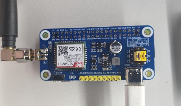
- Install the NB-IoT card into the card slot on the back of the module and connect the LTE antenna. (When in use, rotate the LTE antenna to the outside of the board).
- Connect the Type-C USB cable to the computer's USB port to power the SIM7028 module.
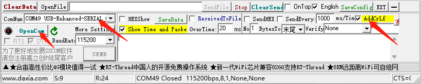
- Open the provided serial port assistant, select the corresponding serial port, and set the baud rate to 115200. Check the "Append CR+LF" option.
- In the extended settings, you will see the AT commands you want to enter. Click on the corresponding command to send it directly.
Basic Networking Test
The following are the common AT commands, you can quickly check whether the AT serial communication of SIM7082 and the network connection are normal.
You should do a simple network test before. Please operate it before checking the network.
A detailed description of the relevant AT commands can be found in the SIM7022 Series_AT Command Manual.
Command | Description | Return value |
AT | AT Test Command | OK |
ATE | ATE1 setup echo mode, ATE0 turns off echo | OK |
AT+CSQ | Query network signal quality, return signal value | OK |
AT+CGMR | Query firmware version | OK |
AT+CGREG? | Query network registration status | OK |
AT+CGACT? | Query PDP status | OK |
AT+COPS? | Query network information | OK |
AT+CGCONTRDP | Query network status | OK |
AT+CFUN=0 | Disable RF | OK |
AT*MCGDEFCONT | Configure APN, such as AT*MCGDEFCONT="IP","3GNET" | OK |
AT+CFUN=1 | Enable RF | OK |
Communication Test
TCP/IP Communication
Here we introduce the SIM7028 module TCP/IP communication function.
SIM7082 module supports transparent transmission mode (data mode), Push Mode, and Buffered Access Mode in non-transparent transmission mode (Command mode).
SIM7082 TCP/IP is a multi-path client structure by default, supporting 2-ch sockets, TCP or UDP.
Before TCP/IP communication, you should make sure the module's networking is normal according to #Hardware Connection and #Basic Networking Test.
SIM7082 module supports TCP and UDP communication, DNS analysis, and Ping function.
(Note: Detailed description of AT commands can be found in SIM7028 Series TCPIP Application Note V1.04, subsequent module firmware upgrade, the corresponding AT commands may be updated.)
【Service】
Related commands:
AT Command | Command Description | Return Value |
AT+NETOPEN | Enable Socket service | OK |
AT+NETCLOSE | Disable Socket service | OK +NETCLOSE: 0 |
AT+CIPOPEN | Multi-link Socket service, up to 2 connections | OK |
AT+CIPSEND | Send data to the destinated connection (TCP, UDP) | OK |
AT+CIPCLOSE | Disable Socket service | OK |
AT+SERVERSTART | Enable TCP server | OK |
AT+SERVERSTOP | Stop TCP server | OK |
【HTTP Client】
Related commands:
AT Command | Command Description | Return Value |
AT+HTTPINIT | Enable HTTP service | OK |
AT+HTTPPARA=URL, https://www.waveshare.net/ | Connect to the remote server | OK |
AT+HTTPDATA=5,1000 | Input data | DOWNLOAD <Type hello OK |
AT+HTTPACTION=0 | Starting the HTTP request, 0:GET; 1:POST; 2:HEAD; 3:DELETE; 4:PUT | OK +HTTPACTION: 0,200,54 |
AT+HTTPTERM | Disable HTTP service | OK |
AT+HTTPPARA | Setup HTTP parameters | OK |
AT+HTTPHEAD | Read HTTP response header information | OK |
AT+HTTPREAD | Read HTTP response information | OK |
【Self-authored interface testing requests using HTTP POST/GET】
Provide test interface: [POST/GET]: [1]/[2].
Here is a simple application case, the POST, write POST and GET requests in a single endpoint, and use the 'request. method' to differentiate and handle the request methods accordingly.
@csrf_exempt
def GET_POST_testapi(request):
    if request.method == 'POST':
        data_value = request.body.decode('utf-8')
        print(data_value)
        if data_value:
            # Storing data into a SQLite database
            data = Data(value=data_value, timestamp=timezone.now())
            data.save()

            max_data_count = 30
            data_count = Data.objects.count()
            if data_count > max_data_count:
                data_to_delete = Data.objects.order_by('timestamp')[:data_count - max_data_count]
                for item in data_to_delete:
                    item.delete()

            return JsonResponse({'message': 'data is saved!'})
        else:
            return JsonResponse({'message': 'Invalid data value'}, status=400)
    elif request.method == 'GET':
        # Access to the latest data
        try:
            latest_data = Data.objects.latest('timestamp')
            response_data = {
                'value': latest_data.value,
                'timestamp': latest_data.timestamp.strftime('%Y-%m-%d %H:%M:%S')
            }
            return JsonResponse(response_data)
        except Data.DoesNotExist:
            return JsonResponse({'message': 'No data available.'})
    else:
        return JsonResponse({'message': 'Invalid request method.'}, status=400)


def get_all_data(request):
    all_data = Data.objects.all().order_by('timestamp')
    timeline = []
    values = []

    for data in all_data:
        try:
            numeric_value = float(data.value)
            timeline.append(data.timestamp.strftime('%Y-%m-%d %H:%M:%S'))
            values.append(numeric_value)
        except ValueError:
            pass  # Ignore values that cannot be converted to numbers

    response_data = {
        'timeline': timeline,
        'value': values
    }

    return JsonResponse(response_data)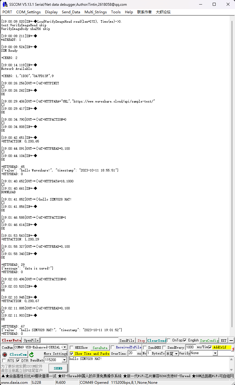
MQTT Communication
Here we mainly introduce the SIM7028 module and MQTT communication.
For more details about AT commands, you can refer to SIM7028 Series MQTT(S) Application Note V1.03
【MQTT Subscribe Topic & Publish Message】
The following is for demonstrating MQTT communication and testing with a private EMQX server connection.
Related commands:
AT Commands | Command Description | Return value |
AT+CMQTTSTART | Enable MQTT service | OK |
AT+CMQTTACCQ=0,"Waveshare-Sim7028",0 | Apply for MQTT client | OK |
AT+CMQTTCONNECT=0,tcp://mqtt.easyiothings.com,20,1 | Send MQTT request, connect to the private MQTT server (MQTTS) | OK |
AT+CMQTTTOPIC=0, 11 | Input message publish topic | >sim7028test OK |
AT+CMQTTPAYLOAD=0,9 | Input the published message | OK >waveshare |
AT+CMQTTPUB=0,0,60 | Publish message | OK +CMQTTPUB: 0,0 |
AT+CMQTTSUB=0,4,1 | Subscribe to the message topic | >test OK +CMQTTSUB: 0,0 [10:03:39.665] receive ←◆ +CMQTTRXSTART: 0,4,18 +CMQTTRXTOPIC: 0,4 test +CMQTTRXPAYLOAD: 0,18 { "msg": "hello" } +CMQTTRXEND: 0 |
AT+CMQTTSTOP | Stop MQTT service | OK |
AT+CMQTTREL | Release client | OK |
AT+CMQTTUNSUBTOPIC | Release subscribed topic | OK |
AT+CMQTTUNSUB | Release subscription | OK |
Note: the AT response time will be as long as the result of the NB-IoT network when testing MQTT commands. Please be patient. For more details, you can refer to MQTT.
Working with Raspberry Pi
Hardware Connection
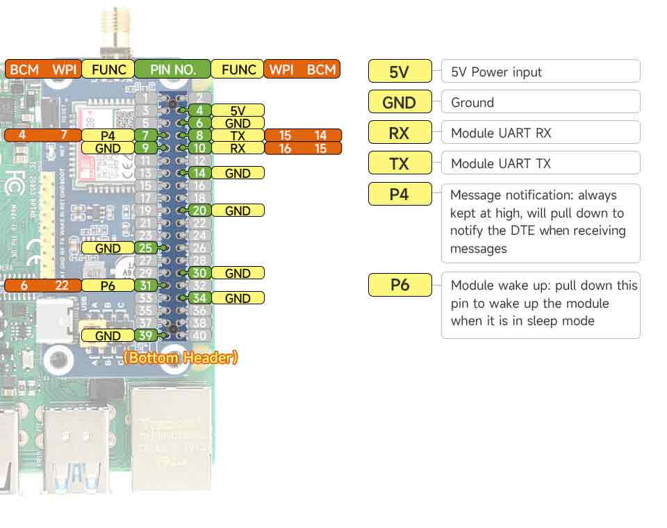
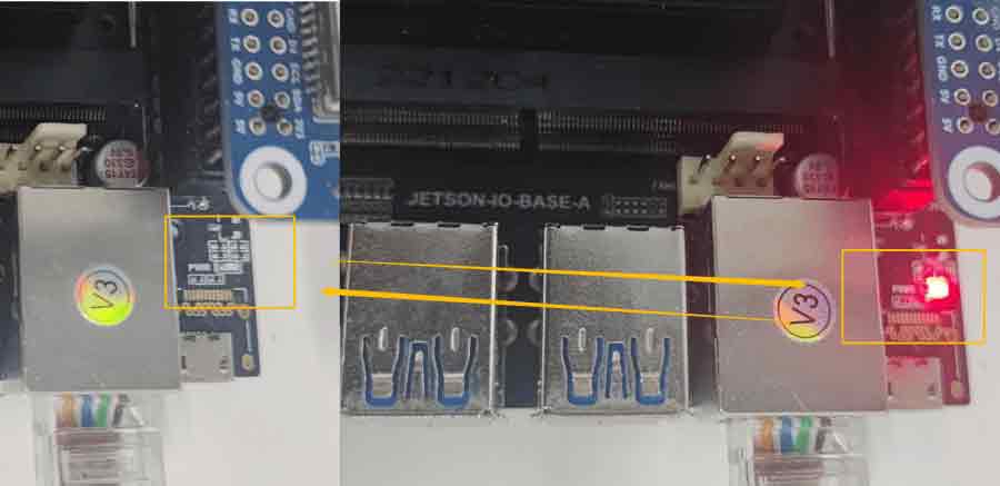
To adjust the jumper cap position to 'B' for the SIM7028 NB-IoT HAT board, please refer to the table below for the Raspberry Pi GPIO pin and module pin connections:
SIM7028 NB-IoT HAT | Raspberry Pi |
5V | 5V |
GND | GND |
RXD | TXD (Corresponding to BCM 14) |
TXD | RXD (Corresponding to BCM 15) |
RI | P7 (Corresponding to BCM 4) |
WAKE | P31 (Corresponding to BCM 6) |
Software Configuration
【UART Configuration】
As the serial ports of the Raspberry Pi are for terminal debugging by default, if you need to use the serial port, you must modify the Raspberry Pi setting.
- Execute the following commands to enter the Raspberry Pi configuration:
sudo raspi-config
- Select Interfacing Option -> Serial -> no -> yes, turn off the UART debugging function.
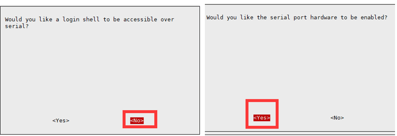
- Reboot it to take effect.
Raspberry Pi Minicom Debugging
Insert the module into the Raspberry Pi, install minicom, and the minicom is the UART debugging tool for Linux:
sudo apt-get install minicom
Execute minicom -D /dev/ttyS0 to enter the minicom serial port debugging interface.
The default baud rate is 115200, ttyS0 is the serial port of Raspberry Pi 3B/3B+/Zero 2, and ttyAMA0 is the serial port of Raspberry Pi Zero.
Press Ctrl + A, Z, and E to type the data without echo.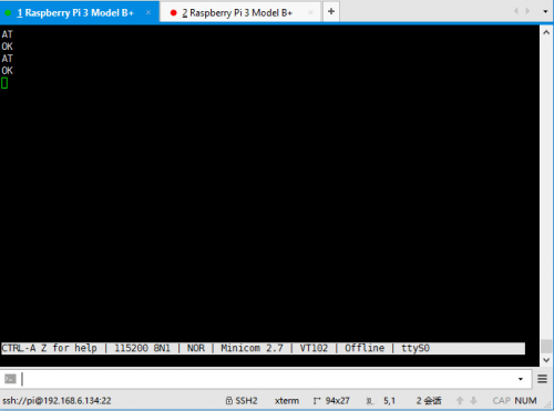
Raspberry Pi Sample Demo
Download the demo and enter the Raspberry Pi directory:
sudo apt-get install unzip -y
wget https://files.waveshare.com/wiki/SIM7028-NB-IoT-HAT/SIM7028-NB-IoT-HAT-Demo-Code.zip
unzip SIM7028-NB-IoT-HAT-Demo-Code.zip -d SIM7028
cd SIM7028/Raspberry/
sudo pip3 install paho-mqtt pyserial
# HTTP request
sudo python3 AT_http_s.py
# MQTT request: pay attention to modifying the corresponding parameters, this MQTT example is to access the WaveshareCloud platform, please refer to the application case for details.
sudo python3 AT_mqtt_s.py
- Sample demo test:
HTTP Request Example: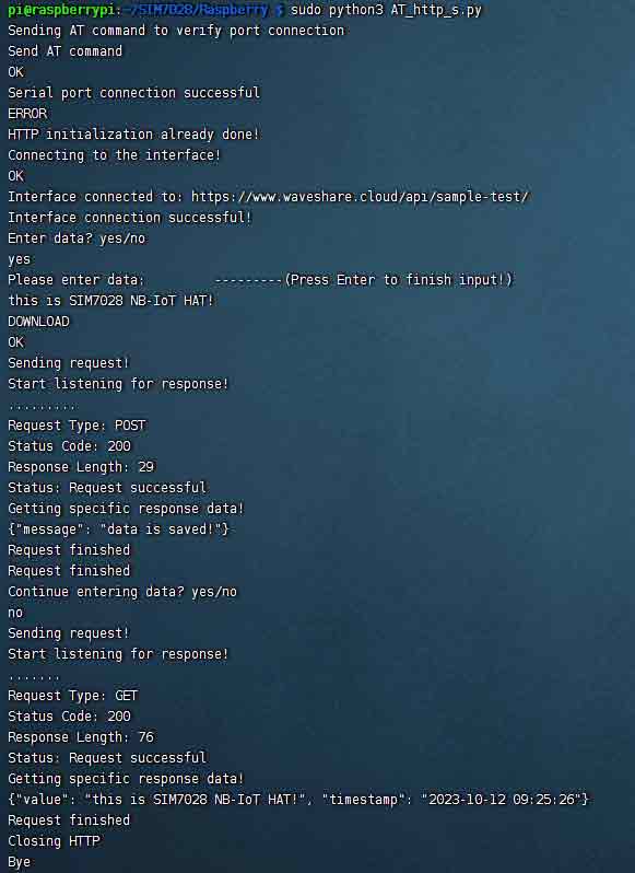
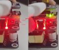
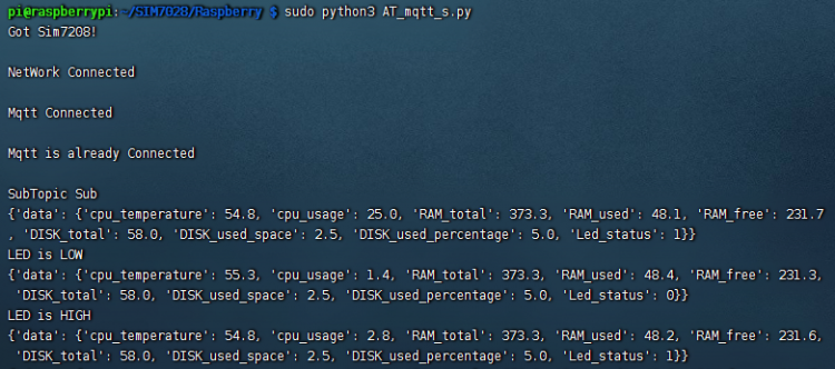
MQTT Request Example:
Connect to Jetson Nano
Hardware Connection
Please refer to the diagram of SIM7028NB-IoT HAT connecting to the Raspberry Pi.
Running Effect
sudo apt-get install unzip -y
wget https://files.waveshare.com/wiki/SIM7028-NB-IoT-HAT/SIM7028-NB-IoT-HAT-Demo-Code.zip
unzip SIM7028-NB-IoT-HAT-Demo-Code.zip -d SIM7028
cd SIM7028/JetsonNano/
sudo pip3 install paho-mqtt pyserial
# HTTP request
sudo python3 AT_http_s.py
#  MQTT request: pay attention to modify the corresponding parameters, this MQTT example is to access the WaveshareCloud platform, see the application case for details.
sudo python3 AT_mqtt_s.py
HTTP Request Example
MQTT Request Example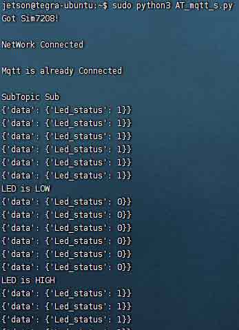
Connect to Arduino/ESP32
Hardware Connection
Arduino can be connected with a software serial port, and ESP32 can be connected with hardware Serial 2.
| Esp32 | Sim7028 NB-IoT HAT | LED |
|---|---|---|
| 5V | VBAT | |
| GND | GND | - |
| Pin16 | TX | |
| Pin17 | RX | |
| Pin4 | RST | |
| Pin5 | + |
Software Configuration
Open Arduino -> File -> Preferences -> Additional Board Manager URLs added. https://www.arduio.cn/package_esp32_index.json
https://dl.espressif.com/dl/package_esp32_index.json
Then open the development board management and search for esp32 to download and install. You can also install arduino-esp32 through the installer, you can find the relevant installation instructions in the Arduino community: Link.
Go to Tools -> Board -> Board Manager to add the esp32 library.
Go to Tools -> Manage Libraries to add "pubsubclient" library and "ArduinoJson" library.
SIM7028 MQTT Request Introduction
MQTT (Message Queuing Telemetry Transport) is a lightweight, publish/subscribe model-based messaging protocol designed to provide reliable and efficient communication for IoT devices.
MQTT Request Components
- Fixed Header: The fixed header of an MQTT message is a mandatory component in every message. It contains essential control information for message transmission, such as message type, Quality of Service (QoS) level, whether the topic should be retained, and more. The fixed header has a fixed length of one byte.
- Variable Header: The variable header of an MQTT message is an optional part, and its length depends on the message type and specific operations. It contains control information related to the message type, such as connection flags and the QoS level of subscribed topics.
- Topic Header: The topic name is a crucial part that identifies the message. When publishing a message, you need to specify a topic name, and subscribers use this topic name to receive messages of interest. Topic names are typically encoded using UTF-8.
- Payload: The payload is the actual data content being transmitted. For published messages, the payload is the data you want to send, and for subscribed messages, the payload is the data received from the publisher. The length of the payload can range from zero bytes up to the maximum message size limit.
MQTT Request Process
- Establish connection:
- The client establishes a connection with the MQTT broker using the TCP/IP protocol. MQTT defaults to using port 1883 for unencrypted connections or port 8883 for encrypted connections (via TLS/SSL).
- Clients have the option to maintain a session, allowing them to recover previous subscriptions and publishing states after disconnecting.
- Publishing Messages:
- As a publisher, the client sends a PUBLISH message to publish a message on a specific topic.
- The PUBLISH message consists of a fixed header, variable header, topic name, and payload (message content).
- After publishing a message, the MQTT broker delivers the message to subscribed clients based on their subscription information.
- Subscribing to Topics:
- As a subscriber, the client sends a SUBSCRIBE message to subscribe to specific topics.
- The SUBSCRIBE message includes a fixed header, variable header, one or more topic filters, and their corresponding Quality of Service (QoS) levels.
- Subscribers can simultaneously subscribe to multiple topics.
- Broker Confirmation of Subscriptions:
- When the broker receives a subscription request, it acknowledges the subscription and stores the corresponding subscription information.
- Subscribers can now receive messages published on the topics they subscribed to.
- Receiving Messages:
- When a new message is published to a topic subscribed by a client, the MQTT broker sends the message to the subscriber.
- Upon receiving the message, the subscriber can process the payload and take appropriate actions.
- Disconnecting:
- After completing communication, clients (publishers or subscribers) can choose to disconnect from the MQTT broker.
- When disconnecting, clients have the option to retain the session, allowing them to preserve previous subscription and publishing states when reconnecting.
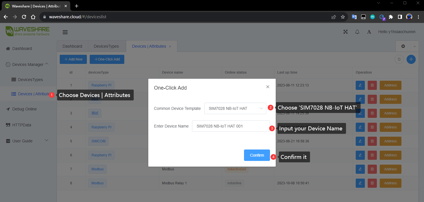
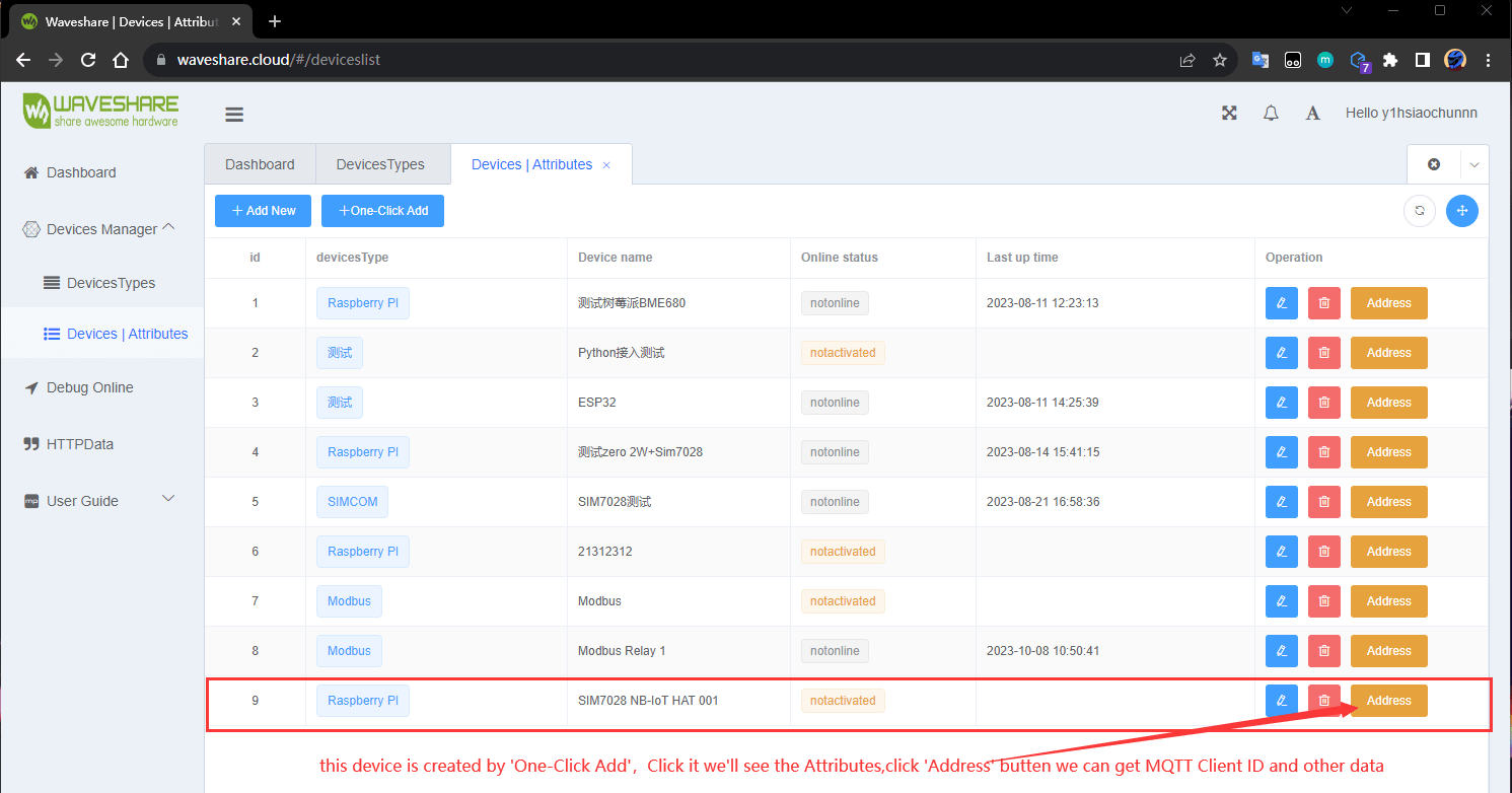
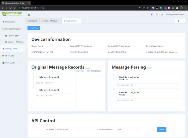
Log in to the platform, create a new device
- To create a specific device, click Add to Device List and fill in the relevant data.
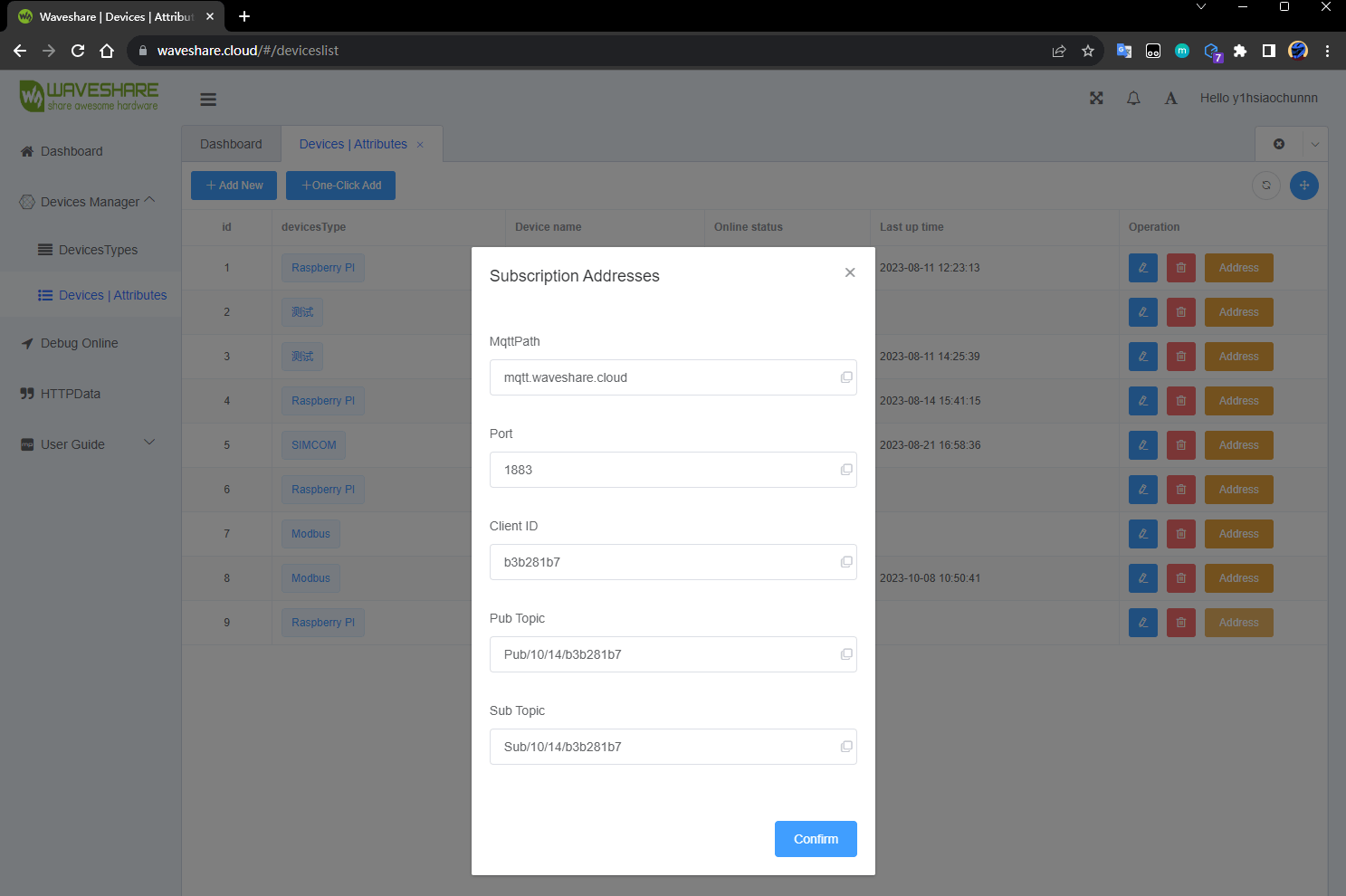
- After the creation of the device is inactive, you can view the contents of the mqtt connection properties through the right address details.
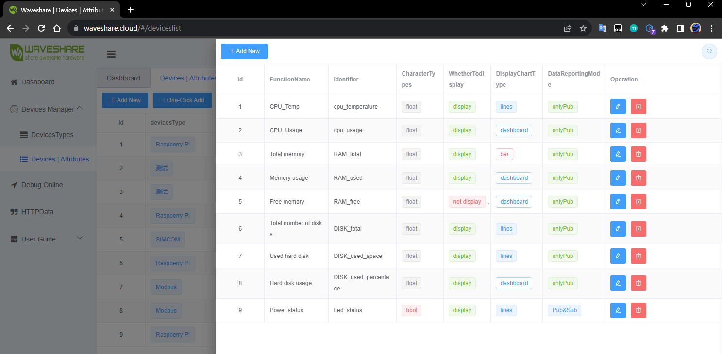
- The device attributes can be uploaded through the need to upload the data content to define the upload, here through a key to add the device that already has LED attributes.
First, use a jumper cap to connect A, that is, the Type-C connects to Sim7028.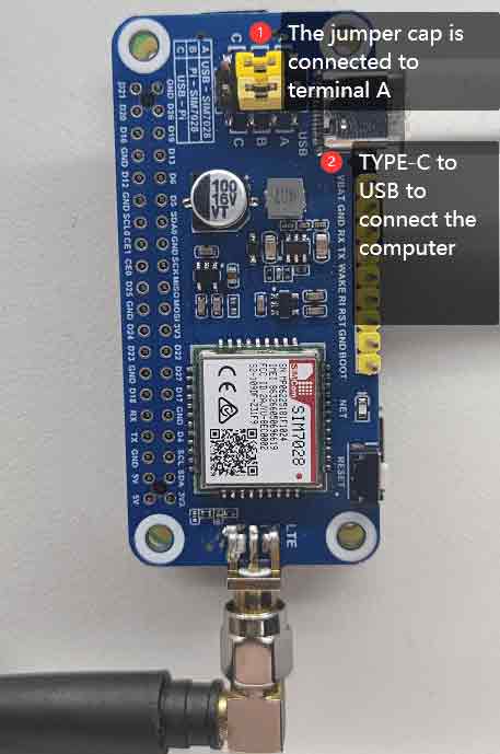
Insert the SIM7028 NB-IoT HAT into the PC with a Type-C to USB cable. Open the serial port using sscom and wait for the network to initialize successfully.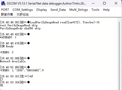
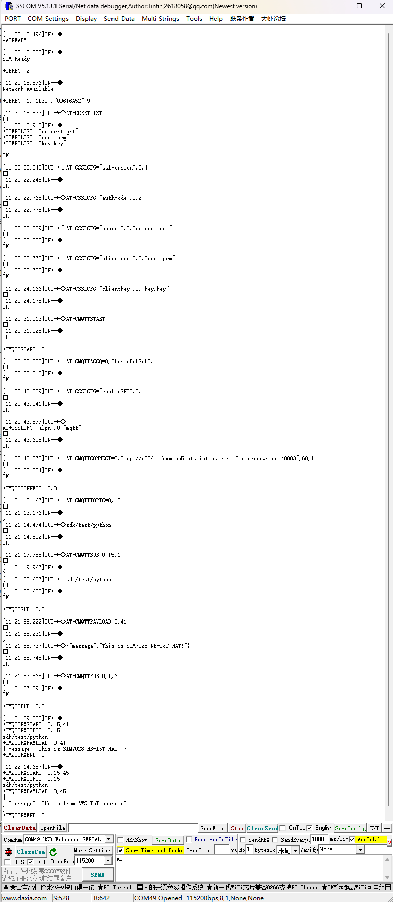
Initialize MQTT Connection
AT+CMQTTSTART
AT+CMQTTACCQ=0,"{Type the client id assigned by the platform}",0
AT+CMQTTCONNECT=0,tcp://mqtt.waveshare.cloud:1883,20,1
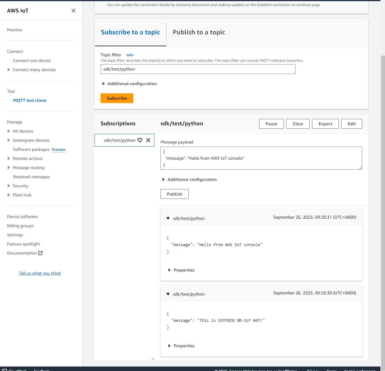
Subscribe & Post Topic
AT+CMQTTTOPIC=0,18 #Type Pub Subject 18 for character length
AT+CMQTTSUB=0,18,0 #Type Sub Subject 18 for character length
Fill in the content of the data to be uploaded:
AT+CMQTTPAYLOAD=0,21 #Character length is less than 10240, here type hello waveshare cloud 21-bit test
Publish:
AT+CMQTTPUB=0,0,60
The screenshot of the overall test data process: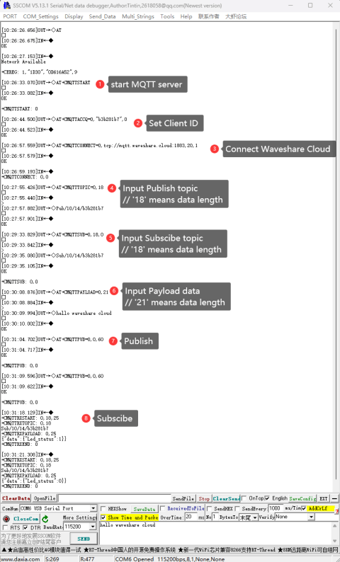
Others
Low-power Mode Details
NB-IoT technology supports three power-saving modes: PSM (Power Saving Mode), DRX (Discontinuous Reception Mode), and eDRX (Extended DRX). In NB-IoT, PSM (Power Saving Mode) and eDRX (Extended Discontinuous Reception) are used to save power. In PSM mode, the terminal doesn't need to actively listen for paging messages to check for downstream data. On the other hand, eDRX mode has longer paging cycles compared to DRX mode, which can result in longer latency and potentially affect the real-time nature of data transmission. The choice between PSM and eDRX depends on the capabilities and configurations of both the terminal device and the network.
Regarding capabilities, it's important not to configure network features that the terminal does not support. Additionally, the terminal's supported capabilities may vary depending on the specific network conditions.
| No | Mode | Description |
|---|---|---|
| 1 | PSM | Extremely save power, and do not receive any data. |
| 2 | DRX | Regularly turn off network services to find the device at any time. |
| 3 | eDRX | eDRX can further reduce the power consumption of NB-IoT devices and extend battery life compared to the traditional DRX mode. However, at the same time, the device may delay when receiving data due to the longer cycle and shorter reception duration of eDRX. |
PSM
In PSM (Power Saving Mode), the terminal does not actively check for paging data in the downlink. PSM mode remains active until either a Tracking Area Update (TAU) or uplink data transmission is required.
| AT command | Description | Return value |
|---|---|---|
| AT+QCPMUCFG=1,4 | Deep sleep mode | OK |
| AT+QCPSMR=1 | Enable low-power URC report | OK |
| AT+CPSMS=1,,,"01011111","00000001" | Setting the PSM mode of the timer | OK |
| AT+CPSMS=0 | Exit PSM mode | OK |
DRX & eDRX
DRX (Discontinuous Reception Mode) can be considered a mode where downstream data can reach the terminal device at any time. Within each DRX cycle (typically set to 1.28 seconds, 2.56 seconds, 5.12 seconds, 10.24 seconds, etc.), the terminal checks for the arrival of downstream data. This mode is suitable for applications with relatively high latency requirements. Terminal devices in this mode are typically powered, such as those used in services like street lighting. Compared to DRX, eDRX (Extended DRX) has longer paging cycles, making the terminal more power-efficient. However, it also comes with longer downstream data latency (e.g., DRX values are 1.28 seconds, and 2.56 seconds, while eDRX values can go up to 20.48 seconds or even 2.9 hours). This makes it ideal for application scenarios where time constraints are not very high.
| AT Command | Description | Return Value |
|---|---|---|
| AT+CEDRXS=1,5,"0010" | Enable eDRX mode | OK |
| AT+CEDRXS? | Query eDRX status | +CEDRXS: 5,"0010" OK |
| AT+CEDRXRDP | Query whether to support | +CEDRXRDP: 5,"0000","0010","0100" |
| AT+CEDRXS=0 | Exit eDRX mode | OK |
Resource
Schematic Diagram
Demo
Software
FAQ
- First check the firmware version of SIM7028, the firmware version is required to be at least 2110B08SIM7028.
- AWS IoT Core requires certificate-based two-way authentication. Of course, you can achieve self-authenticated access using AWS IoT Lambda functions. You can refer to the following steps for certificate-based access: